- 40033332222
- 819698405@qq.com
- 周一至周五 9:00-18:00

制造商:: -
Product datasheet: Datasheet_SHT4x.pdf
Digital humidity & temperature sensor — specification summary
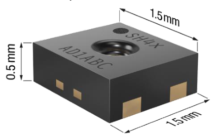
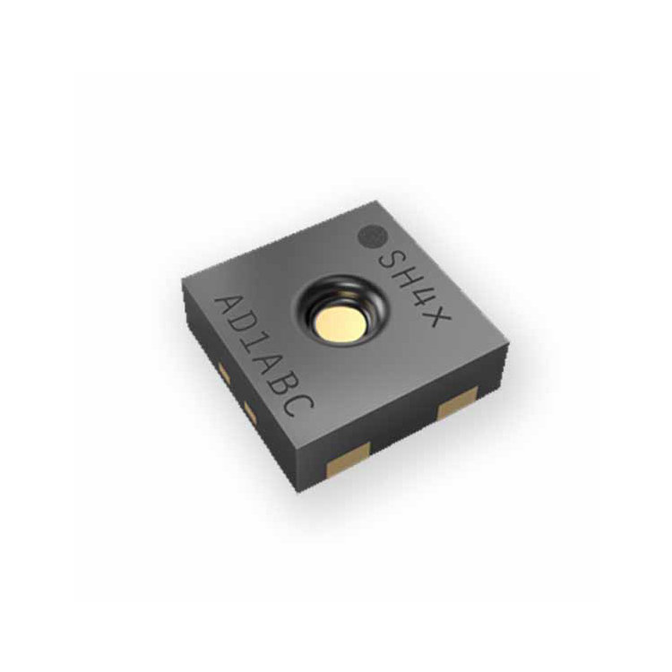
SHT4x is a digital sensor platform for measuring relative humidity and temperature at different accuracy classes. Its I2C interface provides several preconfigured I2C addresses and maintains an ultra-low power budget. The power-trimmed internal heater can be used at three heating levels thus enabling sensor operation in demanding environments. The four-pin dual-flat-no- leads package is suitable for surface mount technology (SMT) processing and comprises an optional on-package patented PTFE [1] membrane or a removable protection cap.
Products Details
SHT40-AD1B base RH&T accur., 0x44 I2C addr.
SHT40-BD1B base RH&T accur., 0x45 I2C addr.
SHT40-AD1F add. patented on-package PTFE
membrane
SHT40-AD1P add. removable protection cap
SHT41-AD1B Intermed. RH&T accur., 0x44 I2C addr. SHT45-AD1B ±1.0 %RH, ±0.1°C accur., 0x44 I2C addr.
Full
1 Quick Start – Hello World ..................................................................................................................................... 3
2 Humidity and Temperature Sensor Specifications ....................................................................................... 4
2.1 Relative Humidity ............................................................................................................................................ 4
2.2 Temperature ..................................................................................................................................................... 6
2.3 Recommended Operating Conditions ...................................................................................................... 7
3 Electrical Specifications ........................................................................................................................................ 8
3.1 Electrical Characteristics .............................................................................................................................. 8
3.2 Timings ............................................................................................................................................................... 9
3.3 Absolute Maximum Ratings ......................................................................................................................... 9
4 Sensor Operation .................................................................................................................................................. 10
4.1 I2C communication ....................................................................................................................................... 10
4.2 I2C Communication Timing ....................................................................................................................... 10
4.3 Data type & length ........................................................................................................................................ 10
4.4 Checksum Calculation ................................................................................................................................. 10
4.5 Command Overview .................................................................................................................................... 11
4.6 Conversion of Signal Output ..................................................................................................................... 11
4.7 Serial number ................................................................................................................................................. 12
4.8 Reset & Abort ................................................................................................................................................. 12
4.9 Heater Operation ........................................................................................................................................... 12
5 Physical Specification .......................................................................................................................................... 13
5.1 Package Description .................................................................................................................................... 13
5.2 Package Outline ............................................................................................................................................ 13
5.3 Land Pattern ................................................................................................................................................... 13
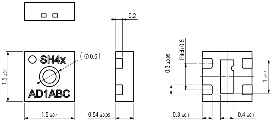
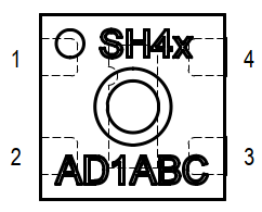
5.4 Pin Assignment & Laser Marking ............................................................................................................. 14
5.5 Thermal Information ..................................................................................................................................... 15
6 Quality and Material Contents ........................................................................................................................... 15
7 Tape and Reel Packaging .................................................................................................................................. 15
8 Product Name Nomenclature ............................................................................................................................ 16
9 Ordering Information ............................................................................................................................................ 16
10 Bibliography .......................................................................................................................................................... 17
11 Revision History .................................................................................................................................................. 17
i2c_write(i2c_addr=0x44, tx_bytes=[0xFD]) wait_seconds(0.01) rx_bytes = i2c_read(i2c_addr=0x44, number_of_bytes=6) t_ticks = rx_bytes[0] * 256 + rx_bytes[1] checksum_t = rx_bytes[2] rh_ticks = rx_bytes[3] * 256 + rx_bytes[4] checksum_rh = rx_bytes[5] t_degC = -45 + 175 * t_ticks/65535 rh_pRH = -6 + 125 * rh_ticks/65535 if (rh_pRH > 100): rh_pRH = 100 if (rh_pRH < 0): rh_pRH = 0
Find code resources and embedded drivers on: https://github.com/Sensirion/embedded- sht/releases
CAD files can be downloaded from SnapEDA: https://www.snapeda.com/search/?q=sht4%3F- &search-type=parts
Long-term drift 8 typ. <0.2 %RH/y
Table 1: General relative humidity sensor specifications.
1 For definition of typ. and max. accuracy, please refer to the document “Sensirion Humidity Sensor Specification Statement”. 2 The stated repeatability is 3 times the standard deviation (3σ) of multiple consecutive measurement values at constant conditions and is a measure for the noise
on the physical sensor output. Different repeatability commands are listed in Table 7.
SHT40 typ
SHT41 typ
SHT40 max
SHT41 max
SHT45 typ
SHT45 max
Relative Humidity (%RH)
Figure 4: SHT45 typical and maximal relative humidity accuracy at 25 °C
SHT41 |typ. Delta %RH|
SHT40 |typ. Delta %RH|
humidity and temperature for SHT41.
SHT45 |typ. Delta %RH|
Temperature (°C)
Figure 7: Typical RH accuracy tolerance over humidity and temperature for SHT45.
max. see Figure 9 -
SHT45 T Accuracy 1 typ. 0.1 °C
Table 2: General temperature sensor specifications.
±1.0
SHT40 typ SHT40 max
SHT41 typ SHT41 max
±0.8
±0.6
±0.4
±0.2
±0.0
Figure 10: SHT45 typical and maximal temperature accuracy.
The sensor shows best performance when operated within the recommended normal temperature and humidity range of 5 °C … 60 °C and 20 %RH … 80 %RH, respectively. Long term exposure to conditions outside recommended normal range, especially at high relative humidity, may temporarily offset the RH signal (e.g. +3 %RH after 60 h at > 80 %RH). After returning into the recommended normal temperature and humidity range the sensor will recover to within specifications by itself. Prolonged exposure to extreme conditions may accelerate ageing. To ensure stable operation of the humidity sensor, the conditions described in the document [2] regarding exposure to volatile organic compounds must be met. Please note as well that this does apply not only to transportation and manufacturing, but also to operation of the SHT4x.
| Parameter | Conditions | Value | Units |
|---|---|---|---|
| typ. | 1.8 | %RH |
| max. | see Figure 2 | - |
|---|---|---|
| typ. | 1.8 | %RH |
| max. | see Figure 3 | - |
|---|---|---|
| typ. | 1.0 | %RH |
| max. | see Figure 4 | - |
|---|---|---|
| high | 0.08 | %RH |
| Repeatability | medium | 0.15 | %RH |
|---|---|---|---|
| low | 0.25 | %RH |
| Resolution | - | 0.01 | %RH | |
|---|---|---|---|---|
| Hysteresis | At 25°C | 0.8 | %RH | |
| Specified range | 5 | extended 6 | 0 to 100 | %RH |
| Response time | 7 | t 63% | 4 | s |
| D RH (%RH) | D RH (%RH) |
|---|---|
| ±8 | ±8 |
| 0 10 20 30 40 50 60 70 80 90 100 | 0 10 20 30 40 50 60 70 80 90 100 |
|---|---|
| Relative Humidity (%RH) | Relative Humidity (%RH) |
| Figure 2: SHT40 typical and maximal relative | Figure 3: SHT41 typical and maximal relative |
| humidity accuracy at 25 °C. | humidity accuracy at 25 °C. |
| D RH (%RH) |
| The typical RH accuracy tolerances in the range of T = 0°C … 80 °C are given in | Figure 5 | , Figure | ||
|---|---|---|---|---|
| 6 and | Figure 7 | . |
| Relative Humidity (%RH) | 50 | 1.8 | Relative Humidity (%RH) | 50 | 1.8 |
|---|---|---|---|---|---|
| 40 | 40 | ||||
| 30 | 30 | ||||
| 20 | 20 |
| 0 | 10 20 30 40 50 60 70 80 | 0 10 20 30 40 50 60 70 80 |
|---|---|---|
| Temperature (°C) | Temperature (°C) | |
| Figure 5: Typical RH accuracy tolerance over | Figure 6: | Typical RH accuracy tolerance over |
| Parameter | Conditions | Value | Units | |
|---|---|---|---|---|
| typ. | 0.2 | °C | ||
| SHT40 T Accuracy | 1 | |||
| max. | see Figure 8 | - | ||
| typ. | 0.2 | °C |
| max. | see Figure 10 | - | ||
|---|---|---|---|---|
| high | 0.04 | °C | ||
| Repeatability | 2 | medium | 0.07 | °C |
| low | 0.1 | °C | ||
| Resolution | 4 | - | 0.01 | °C |
| Specified range | 5 | - | –40 to +125 | °C |
| Response time | t 63% | 2 | s | |
|---|---|---|---|---|
| Long-term drift | 10 | typ. | <0.03 | °C/y |
| -40 -20 0 | 20 40 60 80 100 | 120 | -40 -20 0 | 20 40 60 80 100 120 | |
|---|---|---|---|---|---|
| Temperature (°C) | Temperature (°C) | ||||
| Figure 8: | SHT40 typical and maximal temperature | Figure 9: | SHT41 typical and maximal temperature |
I2C interface with 0x44 address I2C interface with 0x45 address
B package without membrane
Packaging article contains 2’500 pieces
Packaging article contains 10’000 pieces
Table 9 SHT4x product name nomenclature.
| position | value(s) | explanation |
|---|---|---|
| 1 | S | Sensirion |
| 2 | H | Humidity Signal |
| 3 | T | Temperature Signal |
| 4 | 4 | Fourth product generation |
| 0 | Base accuracy | |
| 5 | 1 | Intermediate accuracy |
| 5 | Best accuracy | |
| 6 | - | delimiter |
| 8 | D | DFN package |
|---|---|---|
| 9 | 1 | reserved |
| 10 | F | Package with integrated, patented PTFE membrane | ||
|---|---|---|---|---|
| P | Package with integrated, removable protection cap | |||
| 11 | - | delimiter | ||
| 12 | R | Tape on reel packaging |
Stress levels beyond those listed in Table 5 may cause permanent damage or affect the reliability of the device. These are stress ratings only and functional operation of the device at these conditions is not guaranteed. Ratings are only tested each at a time.
Parameter Rating
Storage temperature range 11 -40 °C …150 °C
ESD HBM 2 kV
Latch up, JESD78 Class II, 125°C +-100 mA
Table 5: Absolute maximum ratings.
| Max. voltage on any pin | V - 0.3 V … | V + 0.3 V |
|---|---|---|
| SS | DD | |
| Operating temperature range | -40 °C … 125 °C |
Parameter Symbol Conditions Min Typ Max Unit Comments
Supply
voltage V DD 1.08 3.3 3.6 V -
Power-
V POR Static power supply 0.6 - 1.08 V -
up/down level
Voltage changes on the
Slew rate of
supply between V DD, min
the supply
V DD, slew - - 20 V/ms
and V DD, max. Faster slew
voltage
rates may lead to a reset
µA At 25°C
Measurement - 320 500 µA Current while sensor is
Supply current
measuring
(no heater) I DD
Aver., high repeatability
Aver. current consumption (continuous operation with
Aver., med. repeatability
one meas. per second)
Aver. power consumption
consumpt. at
(continuous operation with
(no heater)
Aver., low repeatability
input voltage V IL - 0 - 0.3*
Low level
High level
resistors R p
R pullup > 390 Ω - - 0.4 V -
Capacitive bus load can be
R P ≤ 820 Ω: fast mode - - 400 pF
determined from
C b < t rise /(0.8473*R p ).
for fast mode and
VDD > 1.62 V: fast
- - 340 pF
t rise = 120 ns for fast mode
mode plus
plus
Max. values are measured at -40°C and 1.08 V supply voltage (based on characterization).
Parameter Symbol Conditions Min. Typ. Max. Units Comments
Time between V DD reaching V POR and
Power-up time t PU After hard reset,
V DD ≥ V POR - 0.3 1 ms
sensor entering idle
state
Time between ACK of
soft reset command and
Soft reset time t SR After soft reset - - 1 ms
state. Also valid for I2C
general call reset.
t MEAS,l Low
repeatability - 1.3 1.6 ms Including t PU :
The three repeatability
Measurement
t MEAS,m Med.
modes differ with
repeatability - 3.7 4.5 ms
duration
respect to measurement duration, noise level and
t MEAS,h High
repeatability - 6.9 8.3 ms
energy consumption
After that time the heater is automatically switched off
Long pulse 0.9 1 1.1 s
Heater-on duration t Heater
Short pulse 0.09 0.1 0.11 s
Table 4 System timing specifications.
I2C bus operates with 8-bit data packages. Information from the sensor to the master has a checksum after every second 8-bit data package. Humidity and temperature data will always be transmitted in the following way: The first value is the temperature signal (2 * 8-bit data + 8-bit CRC), the second is the humidity signal (2 * 8-bit data + 8-bit CRC).
For read transfers each 16-bit data is followed by a checksum with the following properties
Property Value
Name CRC-8
Message Length 16-bit
0xFD 6 measure T & RH with high precision (high repeatability)
[2 * 8-bit T-data; 8-bit CRC; 2 * 8-bit RH-data; 8-bit CRC]
0xF6 6 measure T & RH with medium precision (medium repeatability)
0xE0 6 measure T & RH with lowest precision (low repeatability) [2 * 8-bit T-data; 8-bit CRC; 2 * 8-bit RH-data; 8-bit CRC]
0x89 6 read serial number
[2 * 8-bit data; 8-bit CRC; 2 * 8-bit data; 8-bit CRC]
activate heater with 200mW for 1s, including a high precision
measurement just before deactivation
activate heater with 200mW for 0.1s including a high precision
activate heater with 110mW for 1s including a high precision
activate heater with 110mW for 0.1s including a high precision
activate heater with 20mW for 1s including a high precision
activate heater with 20mW for 0.1s including a high precision
Table 7 Overview of I2C commands. If the sensor is not ready to process a command, e.g. because it is still measuring, it will response with NACK to the I2C read header. Given heater power values are typical and valid for VDD=3.3V.
| - | - | 3.4 | At 125°C | ||
|---|---|---|---|---|---|
| Power up | - | 50 | - | µA | - |
| Aver., low repeatability | - | 0.4 | - |
|---|---|---|---|
| Aver., high repeatability | - | 2.6 | - |
| input voltage | V DD | |||||
|---|---|---|---|---|---|---|
| Pull up | V DD < 1.62 V | 820 | - | - | Ω | - |
| R > 820 Ω | V | |
|---|---|---|
| pullup | DD | |
| Low level | V DD = 1.62V … 2.0V, | 0.2* |
| output voltage | R pullup > 390 Ω | V DD |
|---|---|---|
| V > 2.0V, |
| C | Rise times are | t = 300 ns |
|---|---|---|
| b | rise |
| Polynomial | 0x31 (x | 8 + x 5 + x 4 +1) |
|---|---|---|
| Initialization | 0xFF | |
| Reflect Input/Output | false/false | |
| Final XOR | 0x00 | |
| Examples | CRC(0xBEEF) = 0x92 |
| Command | Response length | Description |
|---|---|---|
| (hex) | incl. CRC (bytes) | [return values] |
The digital sensor signals correspond to following humidity and temperature values:
A reset of the sensor can be achieved in three ways:
1. The heater is enabled, and the timer starts its count-down. 2. On timer expiration a temperature and humidity measurement with the highest repeatability
is started, the heater remains enabled.
3. After the measurement is finished the heater is turned off.
4. Temperature and humidity values are now available for readout.
The maximum on-time of the heater commands is 1 second in order to prevent overheating of the sensor by unintended usage of the heater. Thus, there is no dedicated command to turn off the heater. For extended heating periods it is required to send periodic heater-on commands, keeping in mind that the heater is designed for a maximal duty cycle of less than 10%. To obtain a fast increase in temperature the idle time between consecutive heating pulses shall be kept minimal.
There will be dedicated Sensirion application notes elaborating on various use cases of the heater. In general, the applications of the on-package heater range around:
1. Removal of condensed / spray water on the sensor surface. Although condensed water is
not a reliability / quality problem to the sensor, it will however make the sensor non- responsive to RH changes in the air as long as there is liquid water on the surface.
2. Creep-free operation in high humid environments. Periodic heating pulses allow for creep-
free high-humidity measurements for extended times.
1. The heater is designed for a maximum duty cycle of 10%, meaning the total heater-on-time
should not be longer than 10% of the sensor’s lifetime.
2. During operation of the heater, sensor specifications are not valid. 3. The temperature sensor can additionally be affected by the thermally induced mechanical
stress, offsetting the temperature reading from the actual temperature.
4. The sensor’s temperature (base temperature + temperature increase from heater) must not
exceed T max = 125 °C in order to have proper electrical functionality of the chip.
6. If higher heating temperatures are desired, consecutive heating commands have to be sent
to the sensor. The heater shall only be operated in ambient temperatures below 65°C else it could drive the sensor outside of its maximal operating temperature.
Figure 12 Dimensional drawing of SHT4x including package tolerances (units mm).
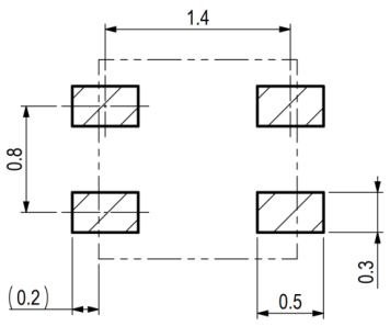
Figure 13: Recommended land pattern
(in mm). Details can vary and depend on used PCBs and solder processes. There
shall be no copper under the sensor
other than at the pin pads.
Heater off, die
Heater on, die
pad
Symbol Description
pad soldered
not soldered
𝑅 𝜃𝐽𝐴 Junction-to-ambient
thermal resistance 246 308 297 357
𝑅 𝜃𝐽𝐶 Junction-to-case
thermal resistance 189 255 191 257
𝑅 𝜃𝐽𝐵 Junction-to-board
thermal resistance 159 225 193 258
Junction-to-board
characterization
param.
Junction-to-top
Table 8 Typical values for thermal metrics. In the “heater on” columns a heater power of 200 mW was assumed. Soldering of the die pad is not recommended, therefore the two right hand side columns are bold. Values are based on simulation.
Qualification of SHT4x is performed based on the JEDEC JESD47 qualification test method, qualification report available on request. The device is fully RoHS and WEEE compliant, e.g. free of Pb, Cd, and Hg. For general remarks of best practice in processing humidity sensor please refer to the handling instructions [2].
| Pin | Name | Comments |
|---|---|---|
| 1 | SDA | Serial data, bidirectional |
| 2 | SCL | Serial clock, unidirectional input |
| 3 | VDD | Supply voltage |
| 4 | VSS | Ground |
base RH&T acc., 0x44 I2C addr.,
SHT40-AD1F-R3 tbd
including patented PTFE membrane
available Q3/22
SHT40-AD1P-R3 tbd
removable protection cap
Table 10 SHT4x ordering options.
[1] K. Ehrhorn, "A Humidity Sensor and a Methode for Manufacturing the Same.". UK, DE, FR, NL, DM, BE, US, CN
Patent EP1810013, US7741950, CN101040181, 2005.
[2] Sensirion, "Handling Instructions for Humidity Sensors," 2020.
Included checksum in Figure 1
Included description of NIST traceability in section 2
Specified serial number in 4.7
Updated qualification status in section 6
Updated ordering information in Table 10
Warning, Personal Injury
Do not use this product as safety or emergency stop devices or in any other application where failure of the product could result in personal injury. Do not use this product for applications other than its intended and authorized use. Before installing, handling, using or servicing this product, please consult the data sheet and application notes. Failure to comply with these instructions could result in death or serious injury.
If the Buyer shall purchase or use SENSIRION products for any unintended or unauthorized application, Buyer shall defend, indemnify and hold harmless SENSIRION and its officers, employees, subsidiaries, affiliates and distributors against all claims, costs, damages and expenses, and reasonable attorney fees arising out of, directly or indirectly, any claim of personal injury or death associated with such unintended or unauthorized use, even if SENSIRION shall be allegedly negligent with respect to the design or the manufacture of the product.
ESD Precautions
The inherent design of this component causes it to be sensitive to electrostatic discharge (ESD). To prevent ESD-induced damage and/or degradation, take customary and statutory ESD precautions when handling this product. See application note “ESD, Latchup and EMC” for more information.
Warranty
This warranty does not apply to any equipment which has not been installed and used within the specifications recommended by SENSIRION for the intended and proper use of the equipment. EXCEPT FOR THE WARRANTIES EXPRESSLY SET FORTH HEREIN, SENSIRION MAKES NO WARRANTIES, EITHER EXPRESS OR IMPLIED, WITH RESPECT TO THE PRODUCT. ANY AND ALL WARRANTIES, INCLUDING WITHOUT LIMITATION, WARRANTIES OF MERCHANTABILITY OR FITNESS FOR A PARTICULAR PURPOSE, ARE EXPRESSLY EXCLUDED AND DECLINED. SENSIRION is only liable for defects of this product arising under the conditions of operation provided for in the data sheet and proper use of the goods. SENSIRION explicitly disclaims all warranties, express or implied, for any period during which the goods are operated or stored not in accordance with the technical specifications. SENSIRION does not assume any liability arising out of any application or use of any product or circuit and specifically disclaims any and all liability, including without limitation consequential or incidental damages. All operating parameters, including without limitation recommended parameters, must be validated for each customer’s applications by customer’s technical experts. Recommended parameters can and do vary in different applications. SENSIRION reserves the right, without further notice, (i) to change the product specifications and/or the information in this document and (ii) to improve reliability, functions and design of this product. Copyright © 2022, by SENSIRION. CMOSens ® is a trademark of Sensirion. All rights reserved
| Material Description | Material Number | Details | Quantity (pcs) | |
|---|---|---|---|---|
| SHT40-AD1B-R2 | 3.000.465 | base RH&T acc., 0x44 I2C addr. | 2’500 | |
| SHT40-AD1B-R3 | 3.000.353 | base RH&T acc., 0x44 I2C addr. | 10’000 |
| SHT40-BD1B-R2 | 3.000.492 | base RH&T acc., 0x45 I2C addr. | 2’500 |
|---|---|---|---|
| SHT40-BD1B-R3 | 3.000.610 | base RH&T acc., 0x45 I2C addr. | 10’000 |
| SHT41-AD1B-R2 | 3.000.466 | intermed. RH&T acc., 0x44 I2C addr. | 2’500 |
| SHT41-AD1B-R3 | 3.000.611 | intermed. RH&T acc., 0x44 I2C addr. | 10’000 |
| SHT45-AD1B-R2 | 3.000.645 | ±1.0 %RH, ±0.1°C acc., 0x44 I2C addr. | 2’500 |
| SHT45-AD1B-R3 | 3.000.750 | ±1.0 %RH, ±0.1°C acc., 0x44 I2C addr. | 10’000 |
| Date | Version | Page(s) | Changes |
|---|---|---|---|
| October 2020 | 1 | all | Initial release |
| July 2021 | 2 | multiple | Typo correction |
| 4 | Included repeatability clarification in | Table 1 |
|---|---|---|
| 10 | Clarified I2C communication in section 4.1 | |
| 9 | Removed waiting time specification in | Table 4 |
| 11 | Deleted binary com. & included return values in | Table 7 |
|---|---|---|
| 12 | Updated note on duty cycle of heater in section 4.9 | |
| 12 | Added note on large current drawn by heater in section 4.9 |
| 16 | Updated ordering information in | Table 10 | ||
|---|---|---|---|---|
| April 2022 | 3 | multiple | Included SHT45 RH- and T-accuracy specifications | |
| multiple | Extended max. heater duty cycle to 10% | |||
| 4 | Reduced RH response time to 4s in | Table 1 | ||
| 4 | Reduced long-term drift to <0.2 %RH/y in | Table 1 |
| 4 | Reduced hysteresis to ±0.8%RH at 25°C in | Table 1 |
|---|---|---|
| 9 | Updated max. measurement times in | Table 4 |
| 10 | Included I2C communication timing in section 4.2 | |
| 16 | Introduced new product version in | Table 9 |
| Sensirion AG | Sensirion Inc., USA | Sensirion Korea Co. Ltd. | |
|---|---|---|---|
| Laubisruetistr. 50 | phone: +1 312 690 5858 | phone: +82 31 337 7700~3 | |
| CH-8712 Staefa ZH | info-us@sensirion.com | info-kr@sensirion.com | |
| Switzerland | www.sensirion.com | www.sensirion.com/kr | |
| phone: | +41 44 306 40 00 | Sensirion Japan Co. Ltd. | Sensirion China Co. Ltd. |
| fax: | +41 44 306 40 30 | phone: +81 3 3444 4940 | phone: +86 755 8252 1501 |
| info@sensirion.com | info-jp@sensirion.com | info-cn@sensirion.com | |
| www.sensirion.com | www.sensirion.com/jp | www.sensirion.com/cn |