- 40033332222
- 819698405@qq.com
- 周一至周五 9:00-18:00


制造商:: -
Product datasheet: SS-盛世物联关于二氧化碳传感器K33.pdf
Digital humidity & temperature sensor — specification summary
Product Specification
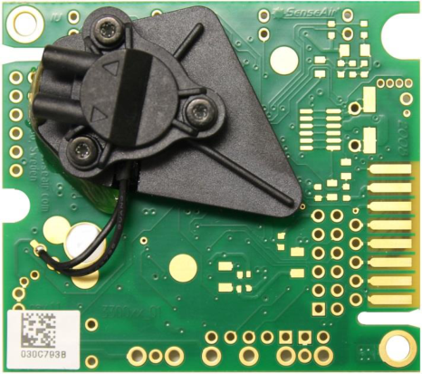
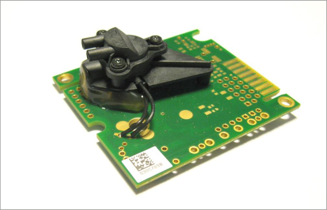
CO 2 Engine ® ICB-F
Sensor module for bio applications
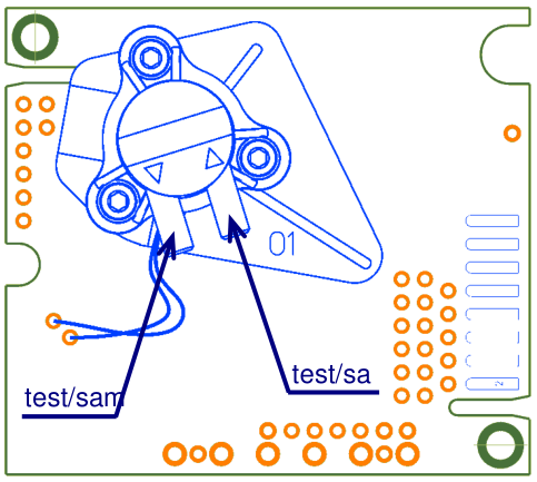
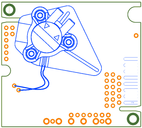
test/sa mple
test/sam ple
Figure 2. CO 2 Engine ® ICB-F Test/sample gas ports
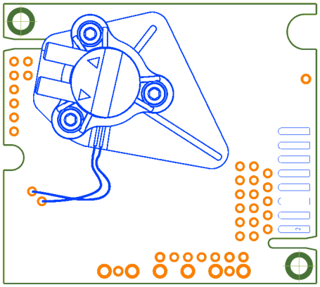
Figure 3. CO 2 Engine ® ICB-F Possible test/sample gas ports installations
Functional group Descriptions and ratings
Power supply (all connection alternatives)
G+ referred to G0
Power supply plus terminal Protected by series 3.3R resistor and zener diode Absolute maximum ratings 5 to 14V, stabilized to within 10%
G0 Power supply minus terminal Sensor’s reference (ground) terminal
DVCC = 3.3V Output from sensor’s digital voltage regulator. Series resistance 10 R Available current 12mA Voltage tolerance (unloaded) +-3% max (+-0.75% typ) Output may be used to power circuit (microcontroller) in host system or to power logical level converter if master processor runs at 5V supply voltage.
Communication
UART (UART_TxD, UART_RxD)
CMOS physical layer, ModBus communication protocol. (refer “ModBus on CO2 Engine K30 rev1_07.pdf” or later version for details) UART_RxD line is configured as digital input. Input high level is 2.1V min Input low level is 0.8V max UART_TxD line is configured as digital output. Output high level is 2.3V (assuming 3.3V DVCC) min. Output low level is 0.75V max UART_RxD input is pulled up to DVCC = 3.3V by 56 kOhm UART_TxD output is pulled up to DVCC = 3.3V by 56 kOhm ABSOLUTE MAX RATING G0-0.5V ….. DVCC + 0.5V
I2C extension. (I2C_SCL, I2C_SDA)
Pull-up to DVCC = 3.3V. (refer “I2C comm guide rev2_00 DRAFT.pdf” or later version for details) ABSOLUTE MAX RATING G0-0.5V ….. DVCC + 0.5V
Outputs
OUT1, OC (Open collector)
Digital output, Open collector Series resistance 120 R Max sink current 40mA May be configured as 1. Alarm indication output 2. PWM output, 10 (alt. 12 to 16) bit resolution. Period 1 .. 1000
msec
3. Pulse length proportional to measured CO2 value.
OUT2 Analog output 0..5V Buffered linear output 0..4 or 1..4VDC or 0..5V or 1..5V, depending on specified power supply and sensor configuration. ROUT < 100 RLOAD > 5 k Load to ground only! Resolution 5mV
Digital I/Os (Used as Inputs in standard configuration. May be implemented as jumper field)
Din0 Din1 Din2
Digital switch inputs in standard configuration, Pull-up 56k to DVCC 3.3V. Driving it Low or connecting to G0 activates input. Pull-up resistance is decreased to 4..10k during read of input or jumper. Advantages are lower consumption most of the time the input/jumper is kept low and larger current for jumpers read in order to provide cleaning of the contact. Can be used for zero or background calibration forcing.
Din3 R/T control line for UART connection to RS485 driver.
Table 1. I/O notations used in this document for the K33 platform with some descriptions and ratings (continue, see previous page). Please, beware of the red colored texts that pinpoint important features for the system integration!
Analogue ground
DGND Digital ground
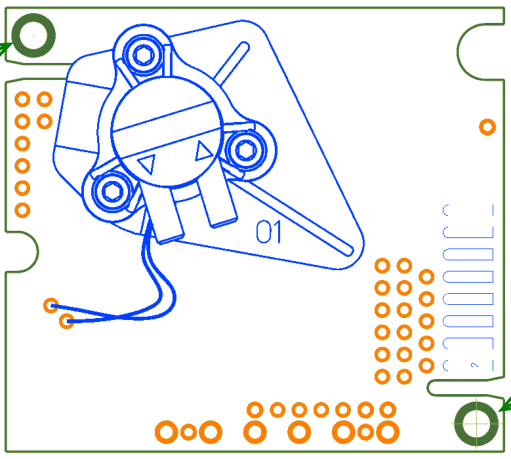
Figure 4. CO 2 Engine ® ICB-F ground / shield attachment
Input Switch Terminal (normally open)
Default function (when closed for minimum 8 seconds)
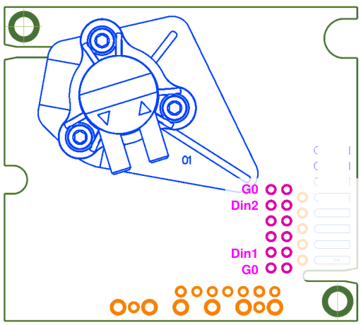
Din1 bCAL (background calibration) assuming 400 ppm CO 2 sensor exposure
Din2 CAL (zero calibration) assuming 0 ppm CO 2 sensor exposure
Table 2. Switch input default configurations for CO 2 Engine ® ICB-F
Din2
Din1
Figure 5. CO 2 Engine ® ICB-F calibration jumpers.
General performance
Target Gas Carbon dioxide (CO 2 )
Storage Temperature Range -40 to +70 °C
Sensor Life Expectancy >15 years
Maintenance Interval Maintenance-free when using SenseAir ABC algorithm (Automatic Baseline Correction)
Self-Diagnostics Complete function check of the sensor module
Warm-up Time 1 min
Conformance with the standards EN 61326-1 (2006), Class B emission, Table 2 Industrial location immunity RoHS directive 2011/65/EU
Operating Temperature Range 0 to +50 °C
Operating Humidity Range Non condensing, non corrosive environment
Operating Environment Residential, commercial, industrial spaces and potentially dusty air ducts used in HVAC (Heating Ventilation and Air- Conditioning) systems 1
Electrical / Mechanical
Power Input 5-14 VDC max rating, stabilized to within 10% (on board protection circuits) 2
Current Consumption 40 mA average < 200 mA average during IR lamp ON (120 msec) < 250 mA peak power (during IR lamp start-up, the first 50 msec)
Electrical Connections 3 terminals not mounted (G+, G0, OUT1, OUT2, Din1, Din2, TxD, RxD)
Dimensions (mm) 5.1 x 5.7 x 1.4 cm (Length x Width x approximate Height)
CO 2 measurement 4
Sensing Method non-dispersive infrared (NDIR) waveguide technology with ABC (automatic background calibration algorithm)
Sampling Method diffusion or flow, subject for discussion with customer
Response Time (T1/e) <20s, diffusion or tube IN/OUT (0.2l/minute gas flow)
Measurement Range 0 to 30% vol
Digital Resolution 0.001% vol
Accuracy 4 5 ± 0.5 %vol. CO 2 ± 3 % of measured value
Pressure Dependence + 1.6 % reading per kPa deviation from normal pressure, 100 kPa
On-Board Calibration Support Din1 switch input to trigger Background Calibration @ 400 ppm (0.04%vol) CO 2 Din2 switch input to trigger Zero Calibration @ 0 ppm CO 2
Linear Signal Output: 4 6
- D/A Resolution 5 mV
- Linear Conversion Range 0 - 5 VDC for 0 – 20%vol.
- Electrical Characteristics ROUT < 100 RLOAD > 5 k , Power input > 5.5 V 6
PWM Output
Electrical Characteristics Open collector with series 120R resistor, 10k pull-up resistor to protected power (+)
Minimum Output Concentration 0% vol
Output Cycle Period 1004 ms
Output High Level min Duration 2.0 ms (@ 0% vol )
Output High Level max Duration 1002 ms (@ 20% vol . )
Resolution 0.5 ms (@0.01% vol = 100 ppm)
Table 2. Key technical specification for CO 2 Engine ® ICB-F
Sensor PWM output timing diagram
Figure 6. CO 2 Engine ® ICB-F OUT1 timing diagram
| 30% CO . This document contains description of default appearance of | CO Engine | ICB-F | . |
|---|---|---|---|
| vol 2 | 2 |
| Item | CO 2 Engine | ICB-F | Art. no:. 033-9-0006 |
|---|---|---|---|
| Repeatability | ± 0.1 %vol. CO | ± 2 % of measured value |