- 40033332222
- 819698405@qq.com
- Mon - Fri 9am - 6pm

Manufacturer:: -
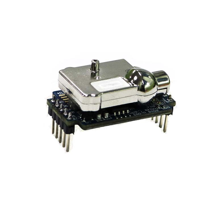
Product datasheet: SS-ZG09S CO2 Module User Manual-20190810.pdf
Digital humidity & temperature sensor — specification summary
Issued
1 Oct 2 2018 JamesHuang Review by Radiant.
1 GENERAL DESCRIPTION ................................................................................................................................................................ 3
2 ABBREVIATIONS AND TERMINOLOGY ......................................................................................................................................... 3
3 FEATURES OF DESIGN ................................................................................................................................................................... 3
4 SPECIFICATION .............................................................................................................................................................................. 3
5 UART ............................................................................................................................................................................................. 6
6 RS485 通訊 ................................................................................................................................................................................ 17
7 I2C 通訊 ..................................................................................................................................................................................... 17
8 PWM 輸出 ................................................................................................................................................................................. 22
9 DAV 輸出 .................................................................................................................................................................................... 22
10 響應時間 ................................................................................................................................................................................. 22
| Version | Date | Author | Description | |
|---|---|---|---|---|
| 1 | Oct 2 2018 | JamesHuang | Review by Radiant. |
超越室內空氣品質需求,量測範圍可達 0-10000ppm
CO2 RMS 雜訊 <10 ppm @ 400 ppm <20 ppm @ 1000 ppm
最大耗電流 (0.8 ms 截取測試 ) <190 mA
紅外線關閉平均耗電流 <10 mA
整體平均耗電流 <34 mA
外觀尺寸 32.2mm x 20.2mm x 10.4mm
UART 3.3V level Modbus RTU protocol
RS485 SCL pin for 485 R/T control pin
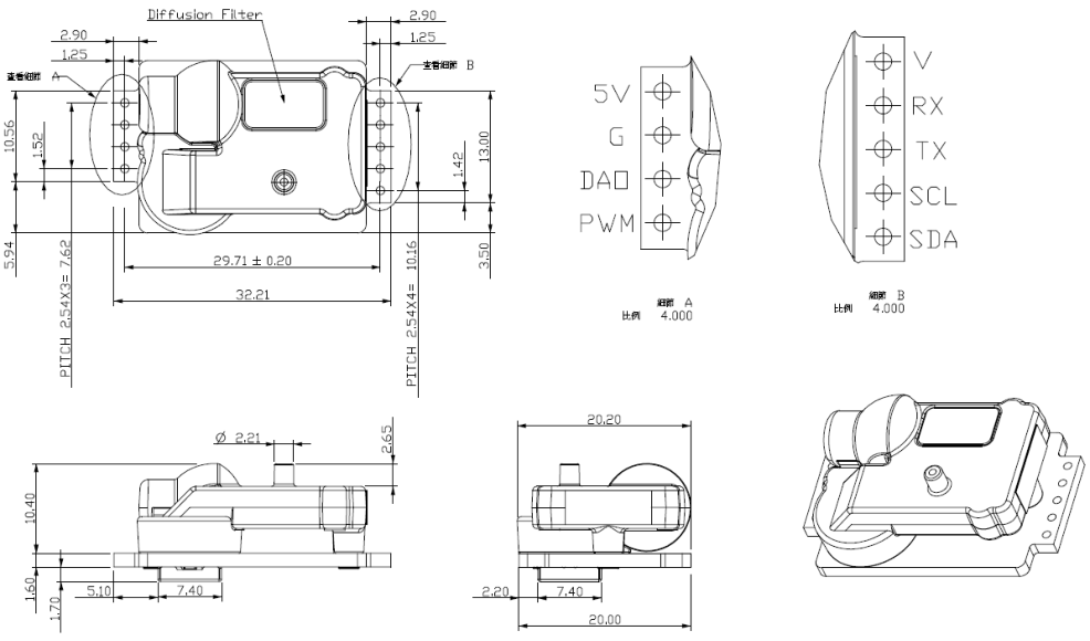
注意:圖片尺寸僅供參考,實際尺寸以標示為主
Fig1. 模組外觀尺寸圖
接腳說明
接腳名稱 功能
PWM CO2 ppm PWM output
DAO DAC output
G Ground
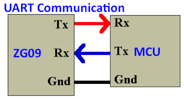
ZG09 series UART 使用的是 Modbus RTU 協議,指令結構分成發送 (Send) 與接收 (Receive) ,如下: 發送 (Send)
发送:FE 03 00 0B 00 01 E1 C7 接收:FE 03 02 01 C8 AC 56 CRC=56AC 接收 (Receive)
Example: CO2 read sequence in Function 3 Master Transmit:
<FE> <03> <00> <0B> <00> <01> <E1> <C7> Slave Reply:
*N = Quantity of Registers
<ID> <Function code> < Byte count byte 0 > <data_byte 0 data_byte n > <CRC byte0 + CRC byte1>
Error:
Error code 1Byte 0x83
註 1 :起始位址 = 想要讀取該筆資料的位址,例如: CO2 值 = 0x0B ( 參見起始位址表 ) 註 2 :讀回資料量 = 資料內容的長度 (N) 註 3 :接收的資料內容的長度 (N) = 發送的讀取資料量 x 2 0x03 Read hold register 0x04 Read input register 0x06 Write CRC 程式範例 :
檢查碼 unsigned int Crc16(unsigned char * data, unsigned char length) {
int j;
unsigned int reg_crc=0xFFFF;
while(length--)
reg_crc ^= *data++;
for(j=0;j<8;j++)
if(reg_crc & 0x01) /* LSB(b0)=1 */
reg_crc=reg_crc >>1 ^ 0xA001;
else
reg_crc=reg_crc >>1;
return reg_crc;
檢查碼 ( 查表法 ) unsigned int Crc(unsigned char *ucTx, unsigned int Len) { if (Len && ucTx)
unsigned char *ucPtr=ucTx;
unsigned char ucCRCHi = 0xff;
unsigned char ucCRCLo = 0xff;
unsigned uIndex;
while(Len--)
uIndex = ucCRCHi ^ *ucPtr++;
ucCRCHi = ucCRCLo ^ ucCRCHigh[uIndex];
ucCRCLo = ucCRCLow[uIndex];
return (unsigned int)(ucCRCLo << 8) | (unsigned int)ucCRCHi;
return 0;
unsigned char ucCRCHigh[] = {
0x00,0xc1,0x81,0x40,0x01,0xc0,0x80,0x41,0x01,0xc0,0x80,0x41,0x00,0xc1,0x81,
0x40,0x01,0xc0,0x80,0x41,0x00,0xc1,0x81,0x40,0x00,0xc1,0x81,0x40,0x01,0xc0,
0x80,0x41,0x01,0xc0,0x80,0x41,0x00,0xc1,0x81,0x40,0x00,0xc1,0x81,0x40,0x01,
0xc0,0x80,0x41,0x00,0xc1,0x81,0x40,0x01,0xc0,0x80,0x41,0x01,0xc0,0x80,0x41,
0xc0,0x80,0x41,0x00,0xc1,0x81,0x40,0x01,0xc0,0x80,0x41,0x00,0xc1,0x81,0x40,
0x40,0x00,0xc1,0x81,0x40,0x01,0xc0,0x80,0x41,0x00,0xc1,0x81,0x40,0x01,0xc0,
0xc0,0x80,0x41,0x01,0xc0,0x80,0x41,0x00,0xc1,0x81,0x40,0x01,0xc0,0x80,0x41,
0x00,0xc1,0x81,0x40,0x00,0xc1,0x81,0x40,0x01,0xc0,0x80,0x41,0x00,0xc1,0x81,
0x40,0x01,0xc0,0x80,0x41,0x01,0xc0,0x80,0x41,0x00,0xc1,0x81,0x40,0x01,0xc0,
0x80,0x41,0x00,0xc1,0x81,0x40,0x00,0xc1,0x81,0x40,0x01,0xc0,0x80,0x41,0x01,
0xc0,0x80,0x41,0x00,0xc1,0x81,0x40,0x00,0xc1,0x81,0x40,0x01,0xc0,0x80,0x41,
unsigned char ucCRCLow[] = {
0x00,0xc0,0xc1,0x01,0xc3,0x03,0x02,0xc2,0xc6,0x06,0x07,0xc7,0x05,0xc5,0xc4,
0x04,0xcc,0x0c,0x0d,0xcd,0x0f,0xcf,0xce,0x0e,0x0a,0xca,0xcb,0x0b,0xc9,0x09,
0x08,0xc8,0xd8,0x18,0x19,0xd9,0x1b,0xdb,0xda,0x1a,0x1e,0xde,0xdf,0x1f,0xdd,
0x1d,0x1c,0xdc,0x14,0xd4,0xd5,0x15,0xd7,0x17,0x16,0xd6,0xd2,0x12,0x13,0xd3,
0x11,0xd1,0xd0,0x10,0xf0,0x30,0x31,0xf1,0x33,0xf3,0xf2,0x32,0x36,0xf6,0xf7,
0x37,0xf5,0x35,0x34,0xf4,0x3c,0xfc,0xfd,0x3d,0xff,0x3f,0x3e,0xfe,0xfa,0x3a,
0x3b,0xfb,0x39,0xf9,0xf8,0x38,0x28,0xe8,0xe9,0x29,0xeb,0x2b,0x2a,0xea,0xee,
0x2e,0x2f,0xef,0x2d,0xed,0xec,0x2c,0xe4,0x24,0x25,0xe5,0x27,0xe7,0xe6,0x26,
0x22,0xe2,0xe3,0x23,0xe1,0x21,0x20,0xe0,0xa0,0x60,0x61,0xa1,0x63,0xa3,0xa2,
0x62,0x66,0xa6,0xa7,0x67,0xa5,0x65,0x64,0xa4,0x6c,0xac,0xad,0x6d,0xaf,0x6f,
0x6e,0xae,0xaa,0x6a,0x6b,0xab,0x69,0xa9,0xa8,0x68,0x78,0xb8,0xb9,0x79,0xbb,
0x7b,0x7a,0xba,0xbe,0x7e,0x7f,0xbf,0x7d,0xbd,0xbc,0x7c,0xb4,0x74,0x75,0xb5,
0x77,0xb7,0xb6,0x76,0x72,0xb2,0xb3,0x73,0xb1,0x71,0x70,0xb0,0x50,0x90,0x91,
0x51,0x93,0x53,0x52,0x92,0x96,0x56,0x57,0x97,0x55,0x95,0x94,0x54,0x9c,0x5c,
0x5d,0x9d,0x5f,0x9f,0x9e,0x5e,0x5a,0x9a,0x9b,0x5b,0x99,0x59,0x58,0x98,0x88,
0x48,0x49,0x89,0x4b,0x8b,0x8a,0x4a,0x4e,0x8e,0x8f,0x4f,0x8d,0x4d,0x4c,0x8c,
0x44,0x84,0x85,0x45,0x87,0x47,0x46,0x86,0x82,0x42,0x43,0x83,0x41,0x81,0x80,
Function code 3 hold register: Address Name REG/EEP Function Description
SlaveID EEP 、 R/W ModBus ID ID 設定 出廠預設 0x01 1~249 for slave 250 (0xFA) and 254 (0xFE) 為廣播預 留,無法設定
01H BPS EEP 、 R/W Baud rate Uart Parity 設定 ( 需要 reset 或重新 上電才會套用 ) 0x00 : 9600 (default) 0x01 : 19200 0x02 : 38400 0x03 : 57600
02H SET EEP 、 R/W Uart Parity Uart Parity 設定 ( 需要 reset 或重新 上電才會套用 ) 0x00:n82 0x01:n81 (default) 0x02:e81 0x03:o81
04H Filter EEP 、 R/W 數位濾波器 0 Enable
2:Hold mode Off Lamp 停止量 CO2
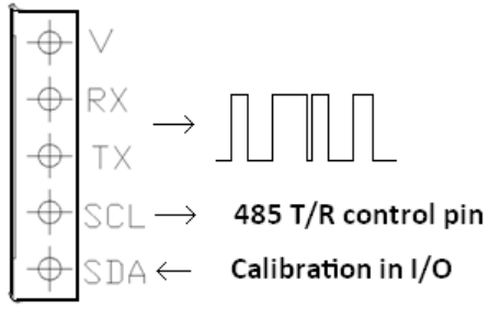
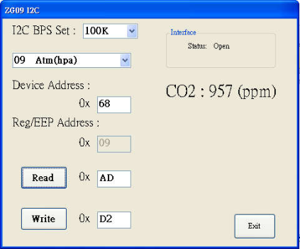
06H I2C ID 6 EEP 、 R/W I2C 位置選擇 1~127(07FH) for I2C slave ID , 255 0FFH for SDA calibration in I/O operating and 485 R/T control pin , 0FFH (default)
0AH Sys status REG 、 R 系統狀態 Read only: 00:Starting 04:Ambinet over operating Temperature 12:CO2 low limit 13:CO2 High Limit 14:Raw Data Error 15Parameter check sum error
0BH CO2 Value REG 、 R CO2 讀值 Read only
0FH Atm Value 1 REG 、 R/W mmHg 氣壓輸入 760.0mmHg(default)
10H Atm Meter 1 REG 、 R/W 高度輸入 0meter(default)
11H Atmhpa 1 REG 、 R/W Hpa 氣壓輸入 1013hpa (default)
14H Control mode 2 REG 、 R/W 控制模式 ( 暫存 ) 0:Polling mode 1:Stream mode 2:Hold mode
15H AL1 3 EEP 、 R/W Lower limit concentration for alarm signal
16H AL2 3 EEP 、 R/W Upper limit concentration for alarm signal
20H CO2 offset EEP 、 R/W CO2 Offset adjustment 新讀值 = 現在 CO2 值 ±1000ppm , 0ppm(default)
21H CO2 Gain EEP 、 R/W Gain range = 0.7~1.3 數學公式:新讀值 = 現在 CO2 值 *Gain 增益 (21H)+offset 偏移 (20H ) 0.7=7000 1.0=10000(default) 1.3=13000
28H Cali Set 4 REG 、 W Any concentration of Gas calibration
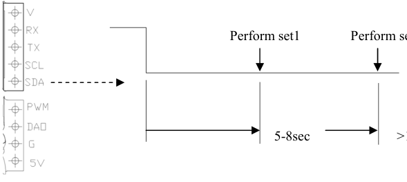
29H Calln Value Set1 5 EEP 、 R/W 400ppm calibration by SDA pin
SDA=0 , 5-8sec for 400ppm offset
2AH Calln Value Set2 5 EEP 、 R/W 0ppm calibration by SDA pin
SDA=0 , >16sec for 0ppm
Master Transmit: <FE> <03> <00> <0F> <00> <01> <A0> <06> Slave Reply: <FE> <03> <02> <1D> <B0> <A4> <B4> 1DB0=7600=760.0mmHg
(b) Write Air Pressure(mmHg) Example input: 730mmHg
Master Transmit: <FE> <06> <00> <0F> <1C> <84> <A5> <65> Slave Reply: <FE> <06> <00> <0F> <1C> <84> <A5> <65> 當寫入 Air pressure (0FH) 730mmHg 同時計算與轉換並存入相對的 Altitude mode(10H) meters 、 Air pressure input (11H) hPa
Read (10H) check Altitude meter value
Master Transmit: <FE> <03> <00> <10> <00> <01> <91> <C0> Slave Reply: <FE> <03> <02> <0C> <EA> <28> <DF> 0CEA=3306=330.6meters
Read (11H) check Air Pressure hpa value
Master Transmit: <FE> <03> <00> <11> <00> <01> <C0> <00> Slave Reply: <FE> <03> <02> <03> <CD> <6D> <35> 03CD=973hpa
Note2: Control mode set has two way, use Addr=5(0x05) Set will set to EEPROM,Power Reset will Keep the Set. Use addr =20 (0x14) Set will only set to Register,Power Reset will clearn the set. (2) Control mode write into EEPROM
(c) 0: Polling mode: 就是一問一答為 ModBus 標準模式
Polling mode operating sequence Master Transmit: <FE> <06> <00> <05> <00> <00> <8D> <C4> Slave Reply: <FE> <06> <00> <05> <00> <00> <8D> <C4> Make sure the settings are correct and the device is running in polling mode.
Slave Reply: <FE> <06> <00> <05> <00> <01> <4C> <04> Make sure the settings are correct and the device is running in Stream mode.
After the command is confirmed, the CO2 value and the Sensor temperature value are returned every 2 seconds. <00> <64> <04> <02> <91> <0B> <85> <74> <22> 0291=657ppm 0B85=29.49 ℃ , 收到 Sensor 溫度需除 100 才為實際溫度 ( 單位為 1/100 ‘ C)
Hold mode operating sequence: Master Transmit: <FE> <06> <00> <05> <00> <02> <0C> <05> This command is written to the EEPROM power off is not canceled must be written to the polling mode Slave Reply: <FE> <06> <00> <05> <00> <02> <0C> <05> Make sure the settings are correct and the device is running in hold mode. At this time, the lamp is off and the CO2
is not measured. The power will not be canceled. Only the CPU waits for the stream or polling mode command to start the lamp and measure CO2 again.
(3) Control mode write into Register
(a) Stream mode operating sequence:
Master Transmit: <FE> <06> <00> <14> <00> <01> <1C> <01> This command is written to the Register Slave Reply: <FE> <06> <00> <14> <00> <01> <1C> <01> Make sure the settings are correct and the device is running in Stream mode.
After the command is confirmed, the CO2 value and the Sensor temperature value are returned every 2 seconds. <00> <64> <04> <02> <91> <0B> <85> <74> <22> 0291=657ppm 0B85=29.49 ℃ , 收到 Sensor 溫度需除 100 才為實際溫度
Hold mode operating sequence: Master Transmit: <FE> <06> <00> <14> <00> <02> <5C> <00> This command is written to the Register Slave Reply: <FE> <06> <00> <14> <00> <02> <5C> <00> Make sure the settings are correct and the device is running in hold mode. At this time, the lamp is off and the CO2
is not measured. The power will be canceled. Or the CPU waits for the stream or polling mode command to start the lamp and measure CO2 again.
Master Transmit: AL1 0ppm <FE> <06> <00> <15> <00> <00> <8C> <01> This command is written to the Register Slave Reply: <FE> <06> <00> <15> <00> <00> <8C> <01> Master Transmit: AL2 10000ppm <FE> <06> <00> <16> <27> <10> <66> <3D> This command is written to the Register Slave Reply: <FE> <06> <00> <16> <27> <10> <66> <3D> Vout: The PWM :0-VCC DAV output: 0-1V
(2) Set AL1 and AL2 sequence: 800~1200ppm for HVAC
Vout
Master Transmit: AL1 800ppm <FE> <06> <00> <15> <03> <20> <8D> <29> This command is written to the EEPROM Slave Reply: <FE> <06> <00> <15> <03> <20> <8D> <29> Master Transmit: AL2 1200ppm <FE> <06> <00> <16> <04> <B0> <7F> <75> This command is written to the Register Slave Reply: <FE> <06> <00> <16> <04> <B0> <7F> <75> Vout: The PWM :0-VCC DAV output: 0-1V
(3) Set AL1 and AL2 sequence: 1400~400ppm for Green Hours
Master Transmit: AL1 1400ppm <FE> <06> <00> <15> <05> <78> <8F> <73> This command is written to the Register Slave Reply: <FE> <06> <00> <15> <05> <78> <8F> <73> Master Transmit: AL2 400ppm <FE> <06> <00> <16> <01> <19> <7D> <FD> This command is written to the Register Slave Reply: <FE> <06> <00> <16> <01> <19> <7D> <FD> Vout: The PWM :0-VCC DAV output: 0-1V
Master Transmit: <FE> <06> <00> <28> <03> <E8> <1D> <73> Slave Reply: <FE> <06> <00> <28> <03> <E8> <1D> <73>
(3) 校正後讀校正後的結果是否接近 1000ppm
Master Transmit: <FE> <03> <00> <0B> <00> <01> <E1> <C7> Slave Reply: <FE> <03> <02> <03> <E9> <6D> <2E> 3E9=1001ppm
ZG09 也可放置於戶外以400ppm 做為標準,人員不要靠近呼吸同時放置10 分鐘後,依照下述方式進行400ppm 校正 。 (1) 如已經放置 10 分鐘 , 寫入 28H 期望值 400ppm
Master Transmit: <FE> <06> <00> <28> <01> <90> <1C> <31> Slave Reply: <FE> <06> <00> <28> <01> <90> <1C> <31>
(2) 校正後讀校正後的結果是否接近400ppm
Master Transmit: <FE> <03> <00> <0B> <00> <01> <E1> <C7> Slave Reply: <FE> <03> <02> <01> <90> <AD> <AC> 190h=400ppm
Master Transmit: <FE> <06> <00> <20> <00> <00> <9C> <0F> Slave Reply: <FE> <06> <00> <20> <00> <00> <9C> <0F>
(2) 讀 ZG09 CO2 值為 1050ppm 多了 55ppm
Master Transmit: <FE> <03> <00> <0B> <00> <01> <E1> <C7> Slave Reply: <FE> <03> <02> <04> <1F> <EF> <58> 41F=1055ppm
(3) 將 -55ppm 的 offset 存入 ZG09
Master Transmit: <FE> <06> <00> <20> <FF> <C9> <1D> <A9> Slave Reply: <FE> <06> <00> <20> <FF> <C9> <1D> <A9>
<FE> <03> <00> <0B> <00> <01> <E1> <C7> Slave Reply: <FE> <03> <02> <03> <E9> <6D> <2E> 3E9=1001ppm
Perform set1 Perform set2
Note6: Address 06H: 0FFH (default) for calibration in I/O operating and 485 R/T control pin
Write in to 1~127 for ID , (07FH) for I2C slave ID , 128~254 no use ,設置後必須關電重啟才會動作或 Reset 。 (1) 設置 I2C ID 下例 ID=68h
Master Transmit: <FE> <06> <00> <06> <00> <68> <7C> <2A> Slave Reply: <FE> <06> <00> <06> <00> <68> <7C> <2A>
(2) Reset or Re-Power 下例為 Reset
<FE> <06> <00> <09> <00> <01> <8C> <07> Slave Reply: <FE> ………….Reset 過程中也會停止傳送 。 UART 與 I2C ID=68h 同時動作 , 使用者可以使用 UART 或 I2C ID=68h
Master Transmit: <FE> <06> <00> <06> <00> <FF> <3D> <84> Slave Reply: <FE> <06> <00> <06> <00> <FF> <3D> <84>
(2) Reset or Re-Power 才會改變 , 下例為 Reset
<FE> <06> <00> <09> <00> <01> <8C> <07> Slave Reply: <FE> ………….Reset 過程中也會停止傳送 。
Note7: ABC 調整預設是關閉 ABC Tune Speed 。是指每日 ABC 自動調整的上限 ( 預設是 100ppm 每天調整量 ) 。防止 ABC 的過度調整 ABC It is recommended to re-open in a well-ventilated environment. This function is not recommended for greenhouses, wine cellars, confined or poorly ventilated spaces, which will affect accuracy. Function 4 input register: Address Name REG/EEP Function Description
00H SYS Status REG 、 R 系統狀態 Read only: 00:Starting 04:Ambinet over operating Temperature 12:CO2 low limit 13:CO2 High Limit 14:Raw Data Error 15Parameter check sum error
Example: CO2 read sequence in Function 4 Master Transmit:
Input Registers N* x 2 Bytes
| CO2 量測範圍 | 0-10000 ppm |
|---|---|
| 量測周期 | 2 sec |
| CO2 精度 (Accuracy) | ±50 ppm ± 3% of reading |
| CO2 再現性 (Repeatability) | ±20 ppm | |
|---|---|---|
| 解析度 (Resolution) | 1ppm | |
| 響應時間 | 擴散式約 | 1min (90% Rise Time) |
| Pressure Dependence | 0.13% of reading per mm Hg |
| I C | Max. clock 400 kHz |
|---|---|
| PWM | 3.3V level at 1 kHz |
| DAC output | 0-1V = 800-1200 ppm |
| SDA | I2C Data pin | 、 0/400ppm calibration pin | |||
|---|---|---|---|---|---|
| SCL | I2C Clock pin or 485 R/T control pin | ||||
| TX | UART TX | ||||
| RX | UART RX | ||||
| V | 3.3V output | 僅給小功率電路使用 | , 如影響量測精度請額外提供 | 3.3V 電源 | 。 |
| UART | 預設 default | |||||
|---|---|---|---|---|---|---|
| BPS: 9600 | 、 Data Bit: 8 、 Parity bit: None | 、 Stop bit: 1 | ||||
| 通訊協定 | (protocol) | |||||
| ZG09 series UART | 使用的是 Modbus RTU | 協議,指令結構分成發送 | (Send) | 與接收 | (Receive) | ,如下: |
| ID | Function code | Starting | Quantity | CRC |
|---|---|---|---|---|
| 編號 | 功能碼 | 起始位址 | 讀取資料量 | 檢查 |
| ( 1 Byte) | ( 1 Byte) | ( 2 Bytes) | ( 2 Bytes) | ( 2 Bytes) |
| 0FEH | 03H | 000BH ( 註 1) | 0001H | XXXX |
| ID | Function code | Byte count | Register value | CRC | |
|---|---|---|---|---|---|
| 編號 | 功能碼 | 讀回資料量 | 資料內容 | 檢查 | |
| ( 1 Byte) | ( 1 Byte) | ( 1 Byte) | ( N Bytes) | ( 2 Bytes) | |
| 0FEH | 03H | 06H ( 註 2) | 6 * 8 bit | ( 註 3) | XXXX |
| Function code | 1Byte | 0x03 |
|---|---|---|
| Starting Address | 2Bytes | 0x0000 to 0xFFFF |
| Quantity of Registers | 2Bytes | 1 to 125 (0x7D) |
| <ID> <Function code> <Starting address byte | + Starting address byte | > <data_byte | + data_byte | > <CRC byte | + CRC_byte | > |
|---|---|---|---|---|---|---|
| 0 | 1 | 0 | 1 | 0 | 1 |
| Function code | 1Byte | 0x03 |
|---|---|---|
| Byte count | 1Byte | 2 x N* |
| Register value | N* x 2 Bytes |
| 註 1 :起始位址 | = 想要讀取該筆資料的位址,例如: | CO2 值 = 0x0B ( | 參見起始位址表 | ) | ||
|---|---|---|---|---|---|---|
| 註 2 :讀回資料量 | = 資料內容的長度 | (N) | ||||
| 註 3 :接收的資料內容的長度 | (N) = | 發送的讀取資料量 | x 2 |
| Address | Name | REG/EEP | Function | Description | ||
|---|---|---|---|---|---|---|
| 00H | SlaveID | EEP 、 R/W | ModBus ID | ID 設定 | 出廠預設 | 0x01 |
| 01H | BPS | EEP 、 R/W | Baud rate | Uart Parity | 設定 ( 需要 reset | 或重新 |
|---|---|---|---|---|---|---|
| 上電才會套用 | ) |
| 02H | SET | EEP 、 R/W | Uart Parity | Uart Parity | 設定 ( 需要 reset | 或重新 |
|---|---|---|---|---|---|---|
| 上電才會套用 | ) |
| 07H | AtmComp | EEP 、 R/W | 氣壓補償 | 1=Enable |
|---|---|---|---|---|
| 09H | Command select | REG 、 W | 命令選項 | 0:Echo 0x1234 |
| 1BH | SN0 | EEP 、 R | 序號 MSB | 16bits Hex code |
|---|---|---|---|---|
| 1CH | SN1 | EEP 、 R | 序號 LSB | 16bits Hex code |
| 1EH | ABC co2 Target | EEP 、 R/W | 環境 CO2 值 | 0~1000ppm | , 400ppm(default) | |
|---|---|---|---|---|---|---|
| 1FH | ABC Day Set | EEP 、 R/W | ABC 調整週期 | 0-30days | 建議設置為 8(default) | |
| 20H | CO2 offset | EEP 、 R/W | CO2 Offset adjustment | 新讀值 | = 現在 CO2 值 ±1000ppm | , |
| 21H | CO2 Gain | EEP 、 R/W | Gain range = | 0.7~1.3 | 數學公式:新讀值 | = 現在 CO2 值 *Gain |
|---|---|---|---|---|---|---|
| 增益 (21H)+offset | 偏移 (20H ) |
| 2FH | ABC Tune Speed | EEP 、 R/W | 每次 | ABC 調整範圍 | 100ppm/day (default) | , 1~300ppm |
|---|---|---|---|---|---|---|
| 7FH | RhOffset | |||||
| 80H | AmbOffset |
| (1) Air pressure input Air Pressure(mmHg) | 、 Altitude mode(meters) | 、 Air pressure input (hPa) |
|---|---|---|
| (a) Read Air Pressure(mmHg) default 760mmHg |
| (d) Stream mode: | 主動發送每 | 2sec 發送一次 | |||
|---|---|---|---|---|---|
| ID | Function code | Byte count | CO2 data | Amb data | CRC |
| 編號 | 功能碼 | 起始位址 | 讀取資料量 | 讀取資料量 | 檢查 |
| ( 1 Byte) | ( 1 Byte) | ( 1 Bytes) | ( 2 Bytes) | ( 2 Bytes) | ( 2 Bytes) |
| 00H | 64H | 04H | 0291H | 0B85H | 7422H |
| 0B85=29.49 | ℃ , 收到 | Sensor 溫度需除 | 100 才為實際溫度 | ( 單位為 | 1/100 | ‘ C) |
|---|---|---|---|---|---|---|
| (e) Hold mode: CO2 | 暫停量測 | ,恢復量測需重設為 | Polling | 或 stream mode | 。 |
| 0B85=29.49 | ℃ , 收到 | Sensor 溫度需除 | 100 才為實際溫度 | |||
|---|---|---|---|---|---|---|
| (b) Hold mode: CO2 | 暫停量測 | ,恢復量測需重設為 | Polling | 或 stream mode or power off | 。 |
| Note3: | AL1 and AL2 for Alarm level setting : | 一般 HVAC 使用為環境 CO2 濃度大於 | AL2 1200ppm( 可自訂 ) 啟動通風。當通風 | |
|---|---|---|---|---|
| 後環境 | 濃度降至 | 可自訂 停止通風。植物栽種使用 | 的方式設定,當植物環境 | 濃度低於 |
| CO2 | 800ppm( ) | AL1>AL2 | CO2 | |
| 400ppm( | 可自訂 ) 增加植物環境 | CO2 濃度,植物環境 | CO2 高於 AL2 1200ppm( 可自訂 | ) 時停止供應 CO2 。 |
| AL1 and AL2 | 的動作影響 | PWM and DAV 的輸出 | , 如為 CO2 讀值使用 AL1 設為 0 , | AL2 設為 3000 或其他範圍 , 輸出電壓 |
| Note4: | Cali Set | 動作說明, ZG09 | 可直接輸入任一氣體標準氣體濃度校正,使用方法為位置 | 28H 寫入已知標準氣體濃度, | ||||
|---|---|---|---|---|---|---|---|---|
| 範圍為現在讀取的濃度 | ±1000ppm(20H) | 解析度 1ppm ,當 | ZG09 接收確認後會立即動作並反應傳回的 | CO2 讀值。 ZG09 | 只 | |||
| 有一個 | offset | 存放的位置 , | 因此 ABC 、 Span 、 Cali Set 都是存放在 | (20H) , 如果 | ZG09(20H) | 有之前校正的記錄 | , 再次校正 |
| 由 ZG09 本身計算 | offset | 偏差量 | , 使用者只要輸入期望值 | . |
|---|---|---|---|---|
| (1) Provide 1000ppm CO2 to ZG09 (Flow rate 100CC/minute) |
| 自己計算 offset | 存入 20H 的程序 | : | |
|---|---|---|---|
| 如已知 CO2 的標準氣體是 | 1000ppm | 圖 ( 提供標準氣體 | ) |
| (1) 清除 ZG09 內部的 | offset value |
| Note5: Calln Value Set1and 2 | , Calibration in value setting 1 | 為 400ppm (default) | 的設定值 | , 可依使用環境需要來設置 | , | |
|---|---|---|---|---|---|---|
| Calibration in value setting 2 | 為 0ppm (default) | 的設定值,也是可以依需要來設置 | 。 |
| , | , | ,設置後必須關電重啟才會動作或 | 。 | ||
|---|---|---|---|---|---|
| Write in to 1~127 for ID | (07FH) for I2C slave ID | 128~254 no use | Reset |
| Address | Name | REG/EEP | Function | Description |
|---|---|---|---|---|
| 00H | SYS Status | REG 、 R | 系統狀態 | Read only: |
| 03H | CO2 Value | REG 、 R | CO2 讀值 | Read only |
|---|---|---|---|---|
| 04H | CO2 AMB | REG 、 R | CO2 sensor temperature | Read only |
| Example: | CO2 read sequence in Function 4 |
| Function code | 1Byte | 0x04 | ||||||
|---|---|---|---|---|---|---|---|---|
| Starting Address | 2Bytes | 0x0000 to 0xFFFF | ||||||
| Quantity of Input Registers | 2Bytes | 0x0001 to 0x007D | ||||||
| <ID> <Function code> <Starting address byte | 0 + Starting address byte | 1 > <data_byte | 0 + data_byte | 1 > <CRC byte | 0 + CRC byte | 1 > |
| <ID> <Function code> < | Byte count byte | > <data_byte | data_byte | > <CRC byte0 + CRC byte1> |
|---|---|---|---|---|
| 0 | 0 | n |
| Error code | 1Byte | 0x84 |
|---|---|---|
| Exception code | 1Byte | 01 or 02 or 03 or 04 |
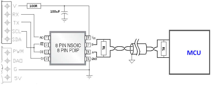
| RS-485/RS422 | (SP3072) | CO2 | ZG09 | ||
|---|---|---|---|---|---|
| 的 3V 輸出電源,如上圖 | ( 圖一 ) 方式連接,接線盡可能縮短, | RL 依照實際上的需要設置 | ,通訊協定依照 | ModBus | 格式 ( 參 |
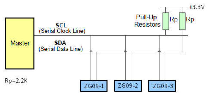
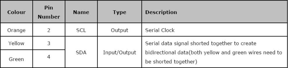
(3) 確認 SCL and SDA 串列訊號線有 pull-up resistors , 如沒有請加入如下圖的電路 , Rp 建議使用 2.2K 。 The ZG09 supports a bi-directional, 2-wire bus and data transmission protocol. A device that sends data onto the bus is defined as a transmitter and a device receiving data as a receiver. The device that controls the message is called a master. The devices that are controlled by the master are referred to as slaves. The bus must be controlled by a master device that generates the serial clock (SCL), controls the bus access, and generates the START and STOP conditions. The ZG09 operates as a slave on the 2- wire bus. A typical bus configuration using this 2-wire protocol is show in Figure 7-1.
Figure7- 1: 2-WIRE BUS CONFIGURATION
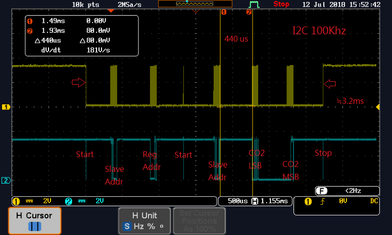
圖二 Data transfer sequence for random Read command Address Name REG/EEP Function Description
02H Sys Status MSB REG 、 R Status register MSB Monitors the operating status--read-only
03H CO2 Value LSB REG 、 R Low-order CO2 concentration data
Read only
0DH Alarm L EEP 、 R/W Lower limit concentration for alarm signal
ppm= Value*10
Write:(0~120)*10;0ppm~1200p pm , set 255 for clear Read for check offset value: 12H for LSB 、 13H for MSB
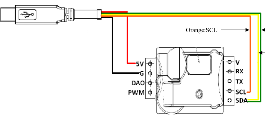
Green:DI Orange:SCL
Yellow:D O
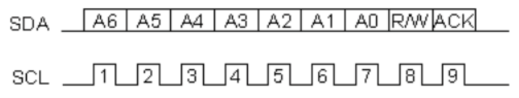
-> 43 (101011)
如果我們要進行寫入 (Write) 的動作的話 我們依照下列的做法 :
1. Send a start sequence 2. Send I2C address with the R/W bit low (even address) 3. Send Internal address of the bearing register 4. Send a start sequence again (repeated start) (with LSB=1) 5. Send I2C address with the R/W bit high (odd address) 6. Read data byte from ZG09 7. Send the stop sequence.
●Data transfer from Master side: ○Data transfer from Slave side:
Data transfer from Master side : 11010000 00000011 11010001 Data transfer 1001000 00000001 Slave side : (97H) (01H)
Register 03H-LSB 04H-MSB
Concentration 01 97H=407ppm
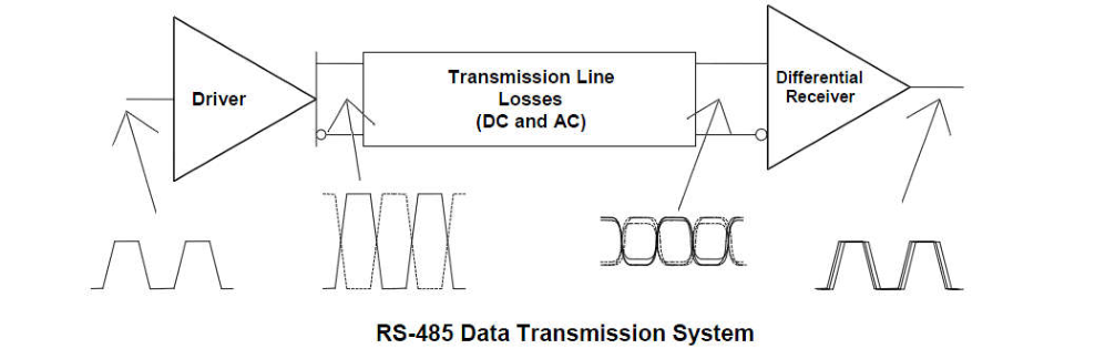
| 由於許多 | RS-485 應用涉及相對較長的電纜長度,因此總線通常被建模為傳輸線,而不是 | “ 集總 ” 連接。 這意味著信號需 | |||
|---|---|---|---|---|---|
| 要不可忽略的時間來通過電纜傳播。通常, | RS-485 系統也必須考慮衰減(信號放大器中的還原) | , 因此 RL 的選擇是為 | |||
| 了通訊的穩定而設置 | , | 當線越長時 | , 減少 RL( | 終端電阻 ) 阻抗 。 | |
| 7 I2C | 通訊 | ||||
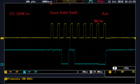
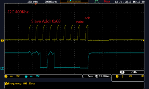
| I2C 界面具有 | 100KHz 以上至 | 400KHz | 的通訊速率 | 。 |
| (1) 使用電腦、樹莓等,透過介面來通訊,需注意 | I/O 的電位 | 0-3.3V | ,但最高不要超過 | 3.5V 。 | |
|---|---|---|---|---|---|
| (2) 使用 CPUs 等不同廠家產品,均可。 | |||||
| (3) 通訊頻率, 100KHZ or 400KHz | ,某些電腦在 100KHz 的通訊頻率時會有不穩定現象,請改至 | 400KHz 通訊。 | |||
| Data Sheet of UART 4 位置 06H 寫入 | 1~127 給 I2C ID 使用,設定完成需重上電。 | ||||
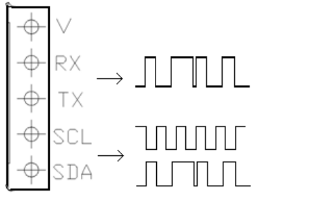
| (1) 1~127(07FH) for I2C slave ID , | 128~254 沒有定義。 | ||||
| (2) 設為 255(0FFH 預設 ) 是給 SDA | 腳做為手動氣體校正 (calibration in I/O operating ) | 或 485 R/T 控制腳,同時關閉 | I2C 。 | ||
| (3) 確認 SCL and SDA 串列訊號線有 | pull-up resistors , 如沒有請加入如下圖的電路 | , Rp 建議使用 2.2K 。 |
| Address | Name | REG/EEP | Function | Description |
|---|---|---|---|---|
| 00H | Reset Set | REG 、 W | Sofware reset | Resets the module |
| 01H | Sys Status LSB | REG 、 R | Status register LSB | Monitors the operating |
| 0AH | Meter | REG 、 R/W | Altitude (Meter) | Value*10 |
|---|---|---|---|---|
| 0BH | Atm (mmHg) | REG 、 R/W | Atmospheric pressure (mmHg) | Atm=Value+520mmHg |
| 0CH | Alarm H | EEP 、 R/W | Upper limit concentration for | ppm=Value *10 |
| 0FH | Filter Set | EEP 、 R/W | 0=Enable | |
|---|---|---|---|---|
| 10H | ABC Day | EEP 、 R/W | ABC cycle time | 0-30 days |
| 11H | ABC Target | EEP 、 R/W | Target CO2 for ABC | (30~120)*10;300ppm~1200ppm |
| 12H | Cali Set | EEP 、 R/W | Any concentration of Gas | Write:(0~120)*10;0ppm~1200p |
|---|---|---|---|---|
| calibration | pm , set 255 for clear |
| for LSB | 、 13H for MSB | ||||
|---|---|---|---|---|---|
| Note1: Cali Set | 動作說明 | , ZG09 可直接輸入任一氣體標準氣體濃度校正 | , 使用方法為位置 | 12H 寫入已知標準氣體濃度 | , |
| 範圍 0ppm~1200ppm | 解析度 10ppm (0~120 | 、 00H~78H)*10ppm | , 當 ZG09 接收確認後會回傳兩筆 | offset 的值 :12H for LSB and | ||
|---|---|---|---|---|---|---|
| , 清除校正值 | 寫入 | 。 | ||||
| 13H for MSB | 12H | 255 (FFH) | ||||
| UART and IC2 | 測試可以使用 | FTDI Cable: 10 | 條 I/O 介面含 | 5V 輸出電源 ( 注意電流輸出需大於 | 200mA 的容量 ) ,通訊與控制 |
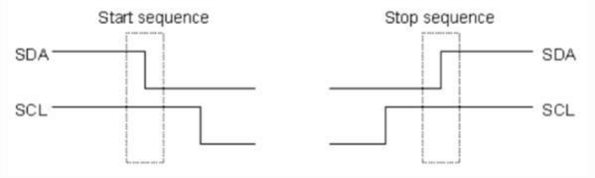
| 簡單的來說,在每次開始的第一步,就是要送 | Start sequence | 到 slave | 然後在要結束前送 | stop | |||
|---|---|---|---|---|---|---|---|
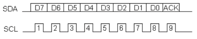
| sequence Data | 8bits | MSB | bit | acknowledge bit |
| 是 | 傳輸 | 是由 | 開始傳輸 | 每八個 | 傳輸完以後會有一個 | ||
|---|---|---|---|---|---|---|---|
| 所以會有 | 9 個 pulse | 。 如果收到的 | ACK bit | 是 low 的話 | 就代表 device | 已經可以準備接收下一筆 |
| 但是如果收到的 | 是 | 的話 就表示不能再接收任何資料 | 此時 | 應該要結束傳 | |
|---|---|---|---|---|---|
| 輸 ( 傳送 stop sequence) | |||||
| 我們馬上可以想到一個問題就是 | I2C 可以傳輸多快呢? | 一般來說 | I2C 的標準是 | 100 KHz, faster | |
| speed mode 可以傳輸高達 | 400 KHz, | 利用 I2C 溝通的時候還要特別注意到一件事情 | 那就是 | Slave | |
| Address: 每一個 I2C device | 都會有自己的 | address (7 bits or 10 bits) | 通常使用 | 7 bits, 10 bits | 很少 |
| 見 , 在 7bits 的情況下的話 | 代表我們最多可以連接 | 128 個 device | 此外我們在傳送的 | mater slave | 的 |
| 資訊的時候還必須在最後面多加上個 | bit R/W 所以送出去的總共還是八個 | bits | 比如說我們要送 |
| 如果我們要進行讀取 | (Read) | 的動作的話 | 我們依照下列的做法 | : 在讀取的部分稍微複雜一些,因為在 | ||||
|---|---|---|---|---|---|---|---|---|
| 讀取之前我們必須要先告訴 | slave | 那個 | internal address | 我們想要讀取 | 所以在讀取之前 | 我們必須要 |
| Start | Start | Stop | |||||
|---|---|---|---|---|---|---|---|
| ● | ● ● | ● ● | ● ● | ○ | ○ | ○ | |
| Slave | Register | Slave | ● |
| SDA | S Address | Address | S Address | P | ||||
|---|---|---|---|---|---|---|---|---|
| ○ | ○ | ○ | ● | ● | ● | ● | ||
| ACK | ACK | ACK | ACK | ACK | ACK |
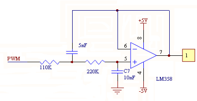
| 可自訂 | 濃度範圍的 | 輸出 | , 運用電路如下圖 | 圖二 , | |||
|---|---|---|---|---|---|---|---|
| CO2 | PWM VCC (3.0~3.3V) level at 1 kHz | 0~10,000ppm | ( ) AL1=0~10,000ppm | ||||
| AL2=0~10,000ppm | 如 AL1<AL2 可使用於 | HVAC | , 運用 | AL1>AL2 可使用於農業 | , 如使用於氣體濃度輸出 | 0~10,000ppm | |
| AL1=0ppm | 、 AL2=10,000ppm |
| 運用 | AL1 0~10,000ppm | AL2 0~10,000ppm | 說明 | |||
|---|---|---|---|---|---|---|
| 監測 | CO2 濃度 | 0ppm (0V) | 10,000ppm (VCC) | |||
| HVAC | 800ppm | 初設 | 1200ppm | 初設 | Note1 | |
| (<800ppm=0V) | (>1200ppm=VCC) | |||||
| 農業 | 自訂 | 自訂 | Note2 |
| 一般 | 使用為環境 濃度大於 | 可自訂 | 啟動通風 。 當通風後環境 | 濃度降至 | 可自 | |
|---|---|---|---|---|---|---|
| Note1: HVAC | CO2 | AL2 1200ppm( | ) | CO2 | 800ppm( | |
| 訂 ) 停止通風 。 | ||||||
| Note2: 植物栽種使用 | AL1>AL2 的方式設定 | , 當植物環境 | CO2 濃度低於 | 400ppm( 可自訂 | ) 增加植物環境 | CO2 濃度 , 植物環 |
| 境 CO2 高於 AL2 1200ppm( | 可自訂 ) 時停止供應 | CO2 。 |
| DAV 輸出是可用戶控制輸出使用 , 不建議做為高精密度 CO2 | 量測使用 , 輸出 0-1V = 初設 800-1200 ppm(~210 階 ) 可藉由 |
|---|---|
| AL1 與 AL2 來控制範圍 , 運用端可以使用比較器來控制繼電器 | , AL2>AL1 可運用於 HVAC , AL1>AL2 運用於農業 , 當 AL1 |
| 設置為 800ppm 此時讀值達 800ppm 時 DAV 輸出 0V , 如希望 | 全範圍輸出可將 AL1 設置為 0ppm 、 AL2 設置為 10000ppm 。 |
| 10 響應時間 | |
| ( 表一 ) 顯示環境 CO2 改變多久時間可以平衡 , 讀值與環境氣體濃度一至 | , 測試方式由 1000ppm 放至 10 分鐘 , 快速移至 |
| 400ppm 環境與 400ppm 放至 10 分鐘 , 快速移至 1000ppm 環境 | 。 |
| ( 表一 ) |
| 400ppm to 1000ppm | ~60sec (90% | 上升時間 | ) |
|---|---|---|---|
| 1000ppm to 400ppm | ~120sec (90% | 下降時間 | ) |
EEP Electrically-Erasable Programmable Read-Only Memory
REG Register
RMS Root Mean Square
PWM Pulse Width Modulation
| I C | Inter-Integrated Circuit |
|---|---|
| HVAC | heating, ventilation and air conditioning |
| RDU | Remote Terminal Unit |