- 40033332222
- 819698405@qq.com
- Mon - Fri 9am - 6pm

Manufacturer:: -
Product datasheet: SS-盛世物联关于森尔S8-0053二氧化碳传感器的产品规格书-20170220.pdf
Digital humidity & temperature sensor — specification summary
Product Specification
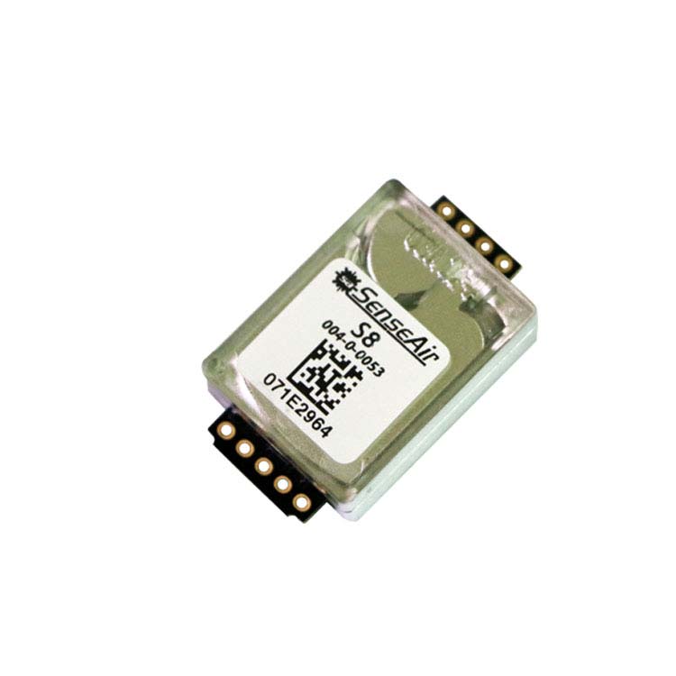
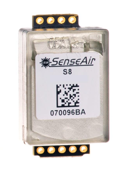
SenseAir ® S8 LP
Miniature infrared CO 2 sensor module
Target gas CO 2
Operating Principle Non-dispersive infrared (NDIR)
Measurement range 400 to 2000 ppm (Note 1). 0 to 10000 ppm extended range (Note 2)
Measurement interval 4 seconds
Accuracy ±40ppm ±3% of reading (Notes 3 and 4)
Pressure dependence + 1.6 % reading per kPa deviation from normal pressure
Response time 2 minutes by 90%
Operating temperature 0 to 50° C
Operating humidity 0 to 85% RH non condensed
Storage temperature -40 to +70 C
Dimensions 33.5 x 20 x 8.5 mm (max dimensions)
Weight < 8 grams
Power supply 4.5 V to 5.25 V unprotected against surges and reverse connection
Power consumption 300 mA peak, < 18 mA average.
Life expectancy 15+ years
Compliance with Emission: EN 61000-6-3:2007, EN 61000-6-4:2007 Immunity: EN 61000-6-1:2007 RoHS directive 2011/65/EU
Serial communication UART, Modbus protocol (Note 5). Direction control pin for direct connection to RS485 receiver integrated circuit.
Alarm output, Open Collector 1000/800 ppm Normal state is conducting max 100 mA. Transistor open at CO 2 High, OR Power Low, OR at Sensor Failure
Alarm state open
PWM output, 1 kHz 0 to 100% duty cycle for 0 to 2000 ppm 3.3V push-pull CMOS output, unprotected
Maintenance Maintenance-free for normal indoor applications with SenseAir ® ABC on.
Table 1. Key technical specification for the SenseAir ® S8 LP __________________________________________________________________
Note 1: Sensor is designed to measure in the range 400 to 2000 ppm with specified in the table accuracy. Nevertheless exposure to concentrations below 400 ppm may result in incorrect operation of ABC algorithm and shall be avoided for model with ABC on.
Note 2: Sensor provides readings via UART in the extended range but the accuracy is degraded compared to specification in the table one.
Note 3: In normal IAQ applications. Accuracy is defined after minimum 3 weeks of continuous operation with ABC. However, some industrial applications do require maintenance. Please, contact SenseAir for further information!
Maximum voltage on Alarm_OC - 0.3 12 V 1,3
Table 2. Absolute maximum ratings specification for the SenseAir ® S8 LP ___________________________________________________________________ Note 1: Specified parameter relies on specification of subcontractor and is not tested by SenseAir
Note 2: Refer chapter “Terminal Description” for rated voltage information
Note 3: Alarm_OC pin is internally pulled up to G+. External pull up to higher voltage will provide resistive divider powering sensor via high resistance.
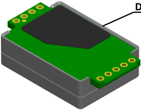
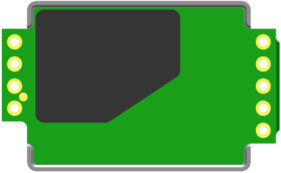
Diffusion area
Figure 2. Diffusion area
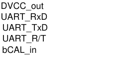
DVCC_out UART_RxD
Alarm_OC
UART_TxD UART_R/T bCAL_in
PWM 1kHz
Pin Function
Power pins
G0 Power supply minus terminal Sensor’s reference (ground) terminal
G+ referred to G0 Power supply plus terminal Operating voltage range
Unprotected against reverse connection! 4.5 V to 5.25 V
Series resistance No internal protection!
Nominal voltage 3.3 VDC
Allowed source current 6 mA max
Voltage precision (Note 1) ± 0.75% is typical, ± 3% is max
Communication pins
Absolute max voltage range (Note 1) G0 - 0.3V to DVCC_out + 0.5V
Internal pull up to DVCC_out resistor 120k
Output low level (Note 1) 0.75 VDC max at 10mA sink
Output high level (Note 1) 2.4 VDC at 2mA source
Absolute max voltage range(Note 1) G0 - 0.3V to DVCC_out + 0.5V
Input low level (Note 1) - 0.3V to 0.75V
Input high level (Note 1) 2.3V to DVCC_out + 0.3V
Input / output
bCAL_in/ CAL Digital input forcing background calibration. Configured as digital input (when closed for minimum 4, max 8 seconds) bCAL (background calibration) assuming 400 ppm CO2 sensor exposure Zero calibration (when closed for minimum 16 seconds) CAL (zero calibration) assuming 0 ppm CO2 sensor exposure
No internal protection, Pulled up to DVCC_out at processor reset (power up and power down)
PWM 1 kHz PWM output Configured as digital output Used for direct reading by customer’s microcontroller or to provide analog output. Refer “Use scenario suggestion” for details and ideas
Duty cycle min 0%, output Low
Duty cycle max 100%, output High
PWM resolution 0.5us ± 4%
PWM period 1ms ± 4%
Internal pull down do G0 resistor 120k
No internal protection, Pulled up to G+ at processor reset (power up and power down)
Absolute max voltage range(Note 1) G0 - 0.3V to 5.5V
Internal pull up to G+ resistor 120k
Max sink current (Note 1) 100 mA
Saturation voltage (Note 1) 2.3V to DVCC_out+0.3V
Warning! ESD
sensitive device!
| Parameter | Minimum | Maximum | Units Notes | |
|---|---|---|---|---|
| Ambient temperature under bias | - 40 | 85 | C | |
| Voltage on G+ pin with respect to G0 pin | - 0.3 | 5.5 | V | 1, 2 |
| Maximum output current from active output pin | - 25 | + 25 | mA | 1 |
| Maximum current on input | - 5 | + 5 | uA | 1 |
| Maximum voltage on UART lines, PWM and bCAL_in | - 0.3 | DVCC_out + | V | 1 |
| The table below specifies terminals and I/O options dedicated in | SenseAir | S8 LP | model. | |
|---|---|---|---|---|
| Pin Function | Pin description / | Electrical specification |
| DVCC_out | from sensor’s voltage regulator | Induced noise or excessive current |
|---|---|---|
| Output may be used to logical level | drawn may affect sensor | |
| converter if master processor runs at | performance. External series | |
| 5V supply voltage. | resistor is strongly recommended if |
| UART_TxD | UART data transmission line | No internal protection |
|---|---|---|
| Configured as digital output | Pulled up to DVCC_out at |
| UART_RxD | UART data receive line | No internal protection |
|---|---|---|
| Configured as digital input | Pulled up to DVCC_out at |
| UART_R/T | Direction control line for half duplex | No internal protection, |
|---|---|---|
| RS485 transceiver like MAX485. | Pulled down at processor reset | |
| Configured as digital output | (power up and power down) | |
| Absolute max voltage range(Note 1) | G0 - 0.3V to DVCC_out + 0.5V | |
| Internal pull down to G0 resistor | 120k | |
| Output low level (Note 1) | 0.75 VDC max at 10mA sink | |
| Output high level (Note 1) | 2.4 VDC at 2mA source |
| bCAL_in/ CAL | Digital input forcing background | No internal protection, |
|---|---|---|
| calibration. Configured as digital input | Pulled up to DVCC_out at |
| PWM 1 kHz | PWM output | No internal protection, |
|---|---|---|
| Configured as digital output | Pulled down at processor reset |
| Alarm_OC | Open Collector output for alarm | No internal protection, |
|---|---|---|
| indication | Pulled up to G+ at processor reset |

ABC parameter Specification
ABC period 8 days
Input Default function
bCAL_in (when closed for minimum 4, max 8 seconds) bCAL (background calibration) assuming 400 ppm CO 2 sensor exposure
CAL_in (when closed for minimum 16 seconds) CAL (zero calibration) assuming 0 ppm CO 2 sensor exposure
Table 5. Switch input default configurations for SenseAir ® S8 LP
Bit # Error code
Error description Suggested action
0 1 Fatal Error Try to restart sensor by power OFF/ON. Contact local distributor.
2 4 Algorithm Error . Indicate wrong configuration.
Try to restart sensor by power OFF/ON. Check detailed settings and configuration with software tools. Contact local distributor.
5 32 Out of Range Error Accompanies most of other errors. Can also indicate overload or failures of sensors and inputs. Resets automatically after source of error disappearance.
Try sensor in fresh air. Perform CO 2 background calibration. Check detailed status of measurements with software tools . See Note 1!
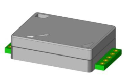
Figure 1. SenseAir ® S8 Article no. 004-0-0017
BeiJing DiHui Technology Co.Ltd
SenseAir® AB
Box 96 Stationsgatan 12 SE- 82060 Delsbo Sweden
Room 1706.Building1. BiXing Garden Luozhuangxili,Zhichun Road Haidian district,Beijing China
| calibration codes. Optional calibrations are | bCAL | (background calibration) | , which requires that | |
|---|---|---|---|---|
| the sensor is exposed to fresh air (400 ppm CO | ) and CAL | (zero calibration), | which requires the |
| 1 | 2 | Reserved | ||
|---|---|---|---|---|
| 2 | 4 | Algorithm Error | . | Try to restart sensor by power OFF/ON. |
| 3 | 8 | Output Error | Check connections and loads of outputs. | |
|---|---|---|---|---|
| Detected errors during output signals | Check detailed status of outputs with | |||
| calculation and generation. | software tools. | |||
| 4 | 16 | Self-Diagnostic Error | . | Check detailed self-diagnostic status with |
| May indicate the need of zero | software tools. Contact local distributor. |
| 5 | 32 | Out of Range Error | Try sensor in fresh air. | |
|---|---|---|---|---|
| Accompanies most of other errors. | Perform CO | background calibration. |
| 6 | 64 | Memory Error | Check detailed settings and configuration |
|---|---|---|---|
| Error during memory operations. | with software tools. | ||
| 7 | 128 | Reserved |
| E-mail: info@senseair.com | Mobile | : 13520502013 |
|---|---|---|
| Web page: www.senseair.com | Phone: +86-(0)10-517 366 16 |