- 40033332222
- 819698405@qq.com
- Mon - Fri 9am - 6pm

Manufacturer:: Panteng Technology
digital and universal particle concentration sensor
Digital humidity & temperature sensor — specification summary
Digital universal particle concentration sensor
PMS7003M series data manual
High anti-interference performance because of the patent structure of six
sides shielding
Optional direction of air inlet and outlet in order to adapt the different
design
Very Slim
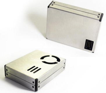
PMS7003M is a kind of digital and universal particle concentration sensor, which can be used to obtain the number of suspended particles in the air, i.e. the concentration of particles, and output them in the form of digital interface. This sensor can be inserted into variable instruments related to the concentration of suspended particles in the air or other environmental improvement equipments to provide correct concentration data in time.
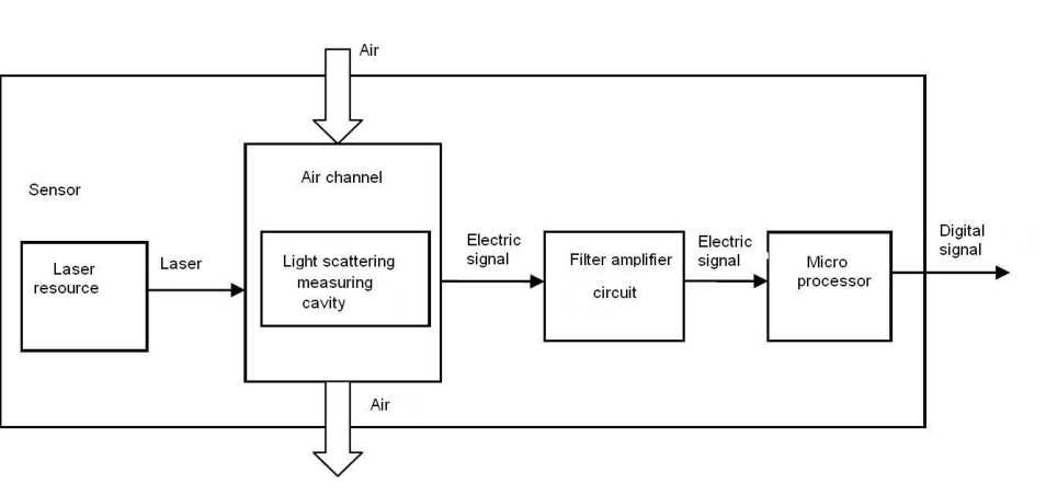
Figure 1 Functional block diagram of sensor
standard )
standard ) *
Working Temperature Range -10~+60 ℃
Working Humidity Range 0~99%
Note 1: Maximum range means that the highest output value of the PM2.5 standard data is not less than 1000. Note 2:“PM2.5 standard data” is the “data2” in the appendix. Pin Definition
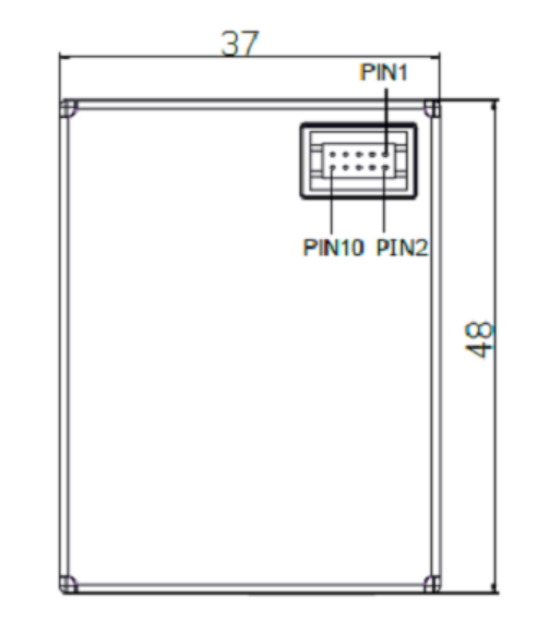
Figure 2 Connector Definition
Output result
Mainly output as the quality and number of each particles with different size per unit volume, the unit volume of particle number is 0.1L and the unit of mass concentration is μ g/m ³ . There are two options for digital output: passive and active. Default mode is active after power up. In this mode sensor would send serial data to the host automatically .The active mode is divided into two sub-modes: stable mode and fast mode. If the concentration change is small the sensor would run at stable mode with the real interval of 2.3s.And if the change is big the sensor would be changed to fast mode automatically with the interval of 200~800ms, the higher of the concentration, the shorter of the interval.
Typical Circuit
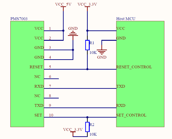
Figure 3 Typical Circuit
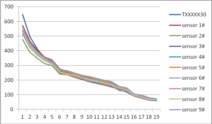
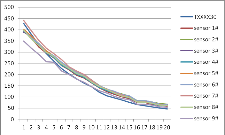
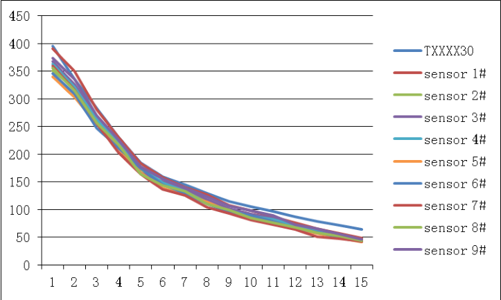
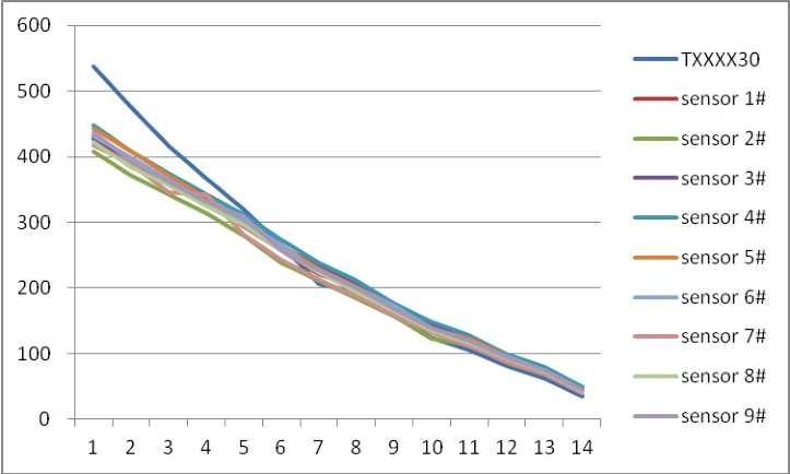
Typical Output Characteristic
Definition of axis Y: PM2.5 concentration , unit: μ g/m ³ Definition of axis X: number of samples, unit: time
Figure 4-1 Consistency at 20 ℃
Figure 4-2 Consistency at 43 ℃
Figure 4-3 Consistency at -5 ℃
Figure 4-4 Consistency after 30 days’ running
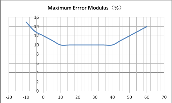
Relationship of Temperature and Consistency
Definition of axis Y: Maximum Error Modulus(%) Definition of axis X: Temperature( ℃ )
Figure 5 Consistency Vs Temperature
Endurance Characteristics
No Item Test Method Characteristics n C
humidity 30%~70% , particle generator and air cleaner
4. DC 5V power supply 5. Check consistency
2. DC 5V power supply and check
consistency
10 samples during 0~500 μ g/m ³ 0~100 μ g/m ³ Maximum Error ≤ ± 10 μ g/m ³ 100~500 μ g/m ³ Maximum Error ≤ ± 10 % FAN does not screeched
6 Cold Storage 1. Constant temperature cabinet 2. -30 ℃, humidity 90%~95 , 3. Check consistency after 500 hours’ storage
50% , particle generator and air cleaner
5. Power varies as the cycles of 4.5V
to 5.5V ,then 5.5V to 4.5V with the pace of 0.1V/min for 2 hours.
6. Check consistency during
Variation
2. DC 5V power supply , keep On-Off
frequency 0.5Hz for 72 hours and check consistency
2. keep laser On-Off frequency
50Hz for 240 hours and check consistency
11 Salt Spray 5% industrial salt water, hydrolysis spray 100 hours, clean with purified water and store for 48 hours
Circuit Attentions
1) DC 5V power supply is needed because the FAN should be driven by 5V.
But the high level of data pin is 3.3V. Level conversion unit should be used if the power of host MCU is 5V.
2) The SET and RESET pins are pulled up inside so they should not be
connected if without usage.
3) PIN7 and PIN8 should not be connected. 4) Stable data should be got at least 30 seconds after the sensor wakeup
from the sleep mode because of the fan’s performance.
Installation Attentions
1) Metal shell is connected to the GND so be careful not to let it shorted with
the other parts of circuit except GND.
2) The best way of install is making the plane of inset and outset closely to
the plane of the host. Or some shield should be placed between inset and outset in order to prevent the air flow from inner loop.
5) The sensor should be installed at least 20cm higher than the grand in
order to prevent it from blocking by the flock dust.
6) Do not break up the sensor.
Other Attentions
1) Only the consistency of all the PM sensors of PLANTOWER is promised
and ensured. And the sensor should not be checked with any third party equipment.
2) The sensor is usually used in the common indoor environment. So some
protection must be added if using in the conditions as followed: a) The time of concentration ≥ 300μ g/m³ is longer than 50% of the
whole year or concentration ≥ 500μ g/m³ i s longer than20% of the whole year.
b) Kitchen c) Water mist condition such as bathroom or hot spring. d) outdoor
Part Number Definition
Hardware Version Min distinguishable particle diameter 03—0.3 micrometer 05—0.5 micrometer 10—1.0 micrometer 25—2.5 micrometer M — inlet and outlet in the front side
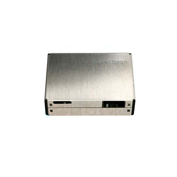
Physical Size (mm)
Frame length low 8
bits
Data 1 high 8 bits …… Data 1 refers to PM1.0 concentration unit μ g/m3 ( CF=1 , standard particle ) * Data 1 low 8 bits ……
Data 2 high 8 bits …… Data 2 refers to PM2.5 concentration unit μ g/m3 ( CF=1 , standard particle ) Data 2 low 8 bits ……
Data 3 high 8 bits …… Data 3 refers to PM10 concentration unit μ g/m3 ( CF=1 , standard particle )
Data 3 low 8 bits ……
Data 4 high 8 bits …… Data 4 refers to PM1.0 concentration unit * μ g/m3 ( under atmospheric environment ) Data 4 low 8 bits ……
Data 5 high 8 bits …… Data 5 refers to PM2.5 concentration unit μ g/m3 ( under atmospheric environment ) Data 5 low 8 bits ……
Data 6 high 8 bits ……. Data 6 refers to concentration unit (under atmospheric environment) μ g/m3 Data 6 low 8 bits ……
Data 7 high 8 bits …… Data 7 indicates the number of particles with diameter beyond 0.3 um in 0.1 L of air. Data 7 low 8 bits ……
Data 8 high 8 bits …… Data 8 indicates the number of particles with diameter beyond 0.5 um in 0.1 L of air. Data 8 low 8 bits ……
Data 9 high 8 bits …… Data 9 indicates the number of particles with diameter beyond 1.0 um in 0.1 L of air.
Data 10 low 8 bits ……
Data 11 high 8 bits …… Data 11 indicates the number of particles with diameter beyond 5.0 um in 0.1 L of air. Data 11 low 8 bits ……
Data 12 high 8 bits …… Data 12 indicates the number of particles with diameter beyond 10 um in 0.1 L of air. Data 12 low 8 bits ……
Data 13 high 8 bits …… Data 13 Reserved
Data 13 low 8 bits ……
Data and check high 8 bits
…… Check code=Start character 1+ Start character 2+……..+data 13 Low 8 bits
Data and check low 8 bits
Host Protocol Start Byte 1
0xe2 X X Read in passive mode
0xe1 X 00H-passive 01H-active
Change mode
0xe4 X 00H-sleep 01H-wakeup
Sleep set
0xe2: 32 bytes , same as appendix I
Add of all the bytes except verify bytes.
| Writer | Zhou Yong | Version | V2.6 |
|---|---|---|---|
| Verifier | Zheng Haoxin | Date | 2017-01-17 |
| Parameter | Index | unit | ||||
|---|---|---|---|---|---|---|
| Range of measurement | 0.3~1.0 | ; 1.0~2.5 | ; 2.5~10 | Micrometer | ( μ m ) |
| Counting Efficiency | 50%@0.3 | m 98%@>=0.5 | m | ||
|---|---|---|---|---|---|
| Effective Range | ( PM2.5 | 0~500 | μ g/m ³ |
| ( | ≥ | μ ³ | |
|---|---|---|---|
| Maximum Range | PM2.5 | 1000 | g/m |
| Maximum Consistency Error | ± 10%@100~500 μ g/m ³ | |
|---|---|---|
| (PM2.5 standard data)* | ± 10 μ g/m ³ @0~100 μ g/m ³ | |
| Standard Volume | 0.1 | Litre ( L ) |
| Single Response Time | < 1 | Second ( s ) |
| ≤ | ( ) | |
|---|---|---|
| Total Response Time | 10 | Second s |
| DC Power Supply | Typ:5.0 Min:4.5 Max: 5.5 | Volt ( V ) |
| Active Current | ≤ 100 | Milliampere ( mA ) |
| Standby Current | ≤ 200 | Microampere ( μ A ) |
| Interface Level | L <0.8 @3.3 H >2.7@3.3 | Volt ( V ) |
| Storage Temperature Range | -40~+80 | ℃ |
|---|---|---|
| MTTF | ≥ 3 | Year ( Y ) |
| Physical Size | ×37×12 | ( ) |
| 48 | Millimeter mm |
| PIN1 | VCC | Positive power 5V |
|---|---|---|
| PIN2 | VCC | Positive power 5V |
| PIN4 | GND | Negative power | |
|---|---|---|---|
| PIN5 | RESET | Module reset signal /TTL level@3.3V | , low |
| PIN7 | RX | Serial port receiving pin/TTL level@3.3V | |
|---|---|---|---|
| PIN8 | NC | ||
| PIN9 | TX | Serial port sending pin/TTL level@3.3V | |
| SET | Set pin /TTL level@3.3V | , high level or |
| 1 | Long Running | 1. 10 ㎡ closed Lab, | , 20~25 ℃, | 10 samples during | n=30 | ||
|---|---|---|---|---|---|---|---|
| humidity 30%~70% | , particle | 0~500 | μ g/m | ³ | C=0 |
| 2. DC 5V power supply | 0~100 | μ g/m | ³ |
|---|---|---|---|
| 3. Check consistency after 720 | Maximum Error | ≤ |
| hours’ running | ± 15 μ g/m | |||||
|---|---|---|---|---|---|---|
| 2 | High | 1. 10 ㎡ constant temperature Lab | n=10 | |||
| ℃, | , | μ | ³ | |||
| Temperature | 2. 43 humidity 70% | 100~500 g/m | C=0 |
| Operation | 3. | and air | Maximum Error | ||
|---|---|---|---|---|---|
| cleaner | ± 15 % | ||||
| 4. DC 5V power supply | |||||
| 5. Check consistency | |||||
| 3 | Cold | 1. 10 ㎡ constant temperature Lab | FAN does not | n=10 |
| 4 | Vibration | 1. 10 ㎡ closed Lab, | , 20 ℃, humidity | n=5 |
|---|---|---|---|---|
| 50% , particle generator | and air | C=0 |
| acceleration | : ²。 | |
|---|---|---|
| 4. | 9.8/ S | |
| 5. Direction | : X 、 Y 、 Z | |
| 6. Vibration Amplitude | :± | 2mm 。 |
| 7. Time : | X 、 Y 、 Z –way, Per 1 hour |
| 5 | High | 1. Constant temperature cabinet | 10 samples during | n=10 | ||||
|---|---|---|---|---|---|---|---|---|
| Temperature | 2. 70 | ℃, humidity 90%~95 | , | 0~500 | μ g/m | ³ | C=0 | |
| and Humidity | 3. Check consistency after 500 | |||||||
| Storage | hours’ | storage | 0~100 | μ g/m | ³ |
| 6 | Cold Storage | 1. Constant temperature cabinet | ± 10 μ g/m | n=10 | |||
|---|---|---|---|---|---|---|---|
| 2. -30 | ℃, | humidity 90%~95 | , | C=0 |
| ㎡ | , ℃, | |||
|---|---|---|---|---|
| 7 | Variation of | 4. 10 closed Lab, | 20 humidity | n=5 |
| Power Supply | 50% , particle generator | and air | C=0 |
| 8 | Power On-Off | 1. 10 ㎡ closed Lab, | , 20 ℃, humidity | n=10 |
|---|---|---|---|---|
| , particle generator | ||||
| Cycle | 50% | and air | C=0 |
| 9 | Sleep Set | 1. 10 ㎡ closed Lab, | , 20 ℃, humidity | n=10 |
|---|---|---|---|---|
| On-Off | 50% , particle generator | and air | C=0 | |
| Cycle | cleaner | |||
| 2. DC 5V power supply | , keep Sleep |
| 10 | Laser On-Off | 1. 10 ㎡ closed Lab, | , 20 ℃, humidity | n=10 |
|---|---|---|---|---|
| Cycle | 50% , particle generator | and air | C=0 |
| 11 | Salt Spray | 5% industrial salt water, hydrolysis | No rust and | n=1 |
|---|---|---|---|---|
| spray 100 hours, clean with | discoloration of |
| a) The time of concentration | ≥ 300μ g/m³ | is longer than 50% of the |
|---|---|---|
| whole year or concentration | ≥ 500μ g/m³ i | s longer than20% of the |
| Sensor Type | Hardware Version | Min distinguishable |
|---|---|---|
| PMS-Particle Matter | particle diameter | |
| Sensor | 03—0.3 micrometer |
| Appendix I | : PMS7003M transport protocol-Active Mode | |||
|---|---|---|---|---|
| Default baud rate | : 9600bps Check bit | : None | Stop bit | : 1 bit |
| Start character 1 | 0x42 | (Fixed) |
|---|---|---|
| Start character 2 | 0x4d | (Fixed) |
| Frame length high | …… | Frame length=2x13+2(data+check bytes) |
| Data 11 low 8 bits | …… | in 0.1 L of air. |
|---|---|---|
| Data 12 high 8 bits …… | Data 12 indicates the number of |
| Appendix II | : PMS7003M transport protocol-Passive Mode | |||
|---|---|---|---|---|
| Default baud rate | : 9600bps Check bit | : None | Stop bit | : 1 bit |
| Start Byte | Start Byte | Command | Data 1 | Data 2 | Verify Byte | Verify Byte | |
|---|---|---|---|---|---|---|---|
| 1 | 2 | 1 | 2 | ||||
| 0x42 | 0x4d | CMD | DATAH | DATAL | LRCH | LRCL | |
| 1. Command Definition | |||||||
| CMD | DATAH | DATAL | comment | ||||
| 0xe2 | X | X | Read in passive |