- 40033332222
- 819698405@qq.com
- Mon - Fri 9am - 6pm

Manufacturer:: -
Product datasheet: SS-盛世物联关于HTU21D温湿度传感器的英文规格书-20191111.pdf
Digital humidity & temperature sensor — specification summary
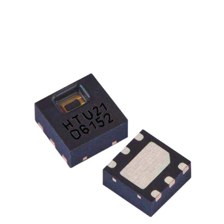
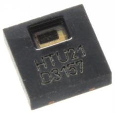
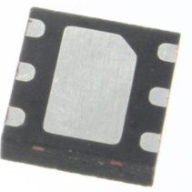
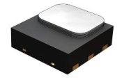
The HTU21D(F) is a new digital humidity sensor with temperature output by MEAS. Setting new standards in terms of size and intelligence, it is embedded in a reflow solderable Dual Flat No leads (DFN) package with a small 3 x 3 x 0.9 mm footprint. This sensor provides calibrated, linearized signals in digital, I²C format.
With MEAS’ improvements and miniaturization of this sensor, the performance-to-price ratio has been improved – and eventually, any device should benefit from its cutting-edge energy saving operation mode.
Optional PTFE filter/membrane (F) protects HTU21D digital humidity sensors against dust and water immersion, as well as against contamination by particles. PTFE filter/membranes preserve a high response time. The white PTFE filter/membrane is directly stuck on the sensor housing. This membrane is allowing an IP67 compliant protection.
HTU21D(F) digital humidity sensors are dedicated humidity and temperature plug and play transducers for OEM applications where reliable and accurate measurements are needed. Direct interface with a micro-controller is made possible with the module for humidity and temperature digital outputs. These low power sensors are designed for high volume and cost sensitive applications with tight space constraints.
Every sensor is individually calibrated and tested. Lot identification is printed on the sensor and an electronic identification code is stored on the chip – which can be read out by command. Low battery can be detected and a checksum improves communication reliability. The resolution of these digital humidity sensors can be changed by command (8/12bit up to 12/14bit for RH/T).
With embedded PTFE filter: HTU2XYF
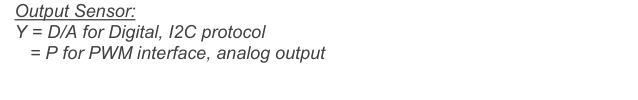
Output Sensor: Y = D/A for Digital, I2C protocol = P for PWM interface, analog output
Humidity accuracy : X = 0: +/-5%RH max tolerance @55%RH = 1: +/-3%RH max tolerance @55%RH
HTU2XY Modules HTU2XYF Modules

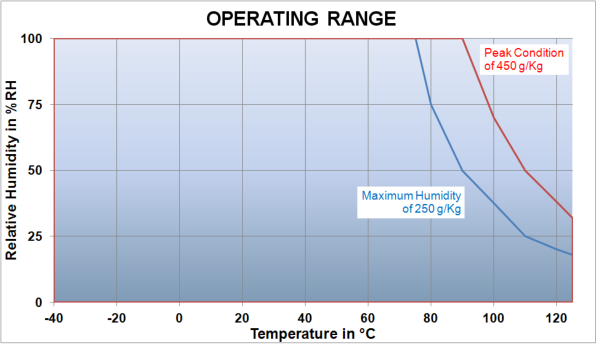
Maximum Ratings
Graph above show peak conditions : less than 10% of the operating life
Exposure to absolute maximum rating conditions for extended periods may affect the sensor reliability.
(@T = 25°C, @Vdd = 3V)
Average 8bit (2) 2.7 µW
Communication digital 2-wire interface, I²C protocol
(2) Conditions: V dd = 3V, SCK= 400kHz, Temp<60°C, duty cycle <10%
Relative Humidity
Measuring Time (1)
(1) Typical values are recommended for calculating energy consumption while maximum values shall be applied for calculating waiting times in communication.
(2) At 1m/s air flow
| Ratings | Symbol | Value | Unit |
|---|---|---|---|
| Storage Temperature | T stg | -40 to 125 | °C |
| Supply Voltage (Peak) | V | 3.8V | V |
| cc | dc | ||
| Humidity Operating Range | RH | 0 to 100 | %RH |
| T | -40 to +125 | °C | |
| Temperature Operating Range | a | ||
| -0.3 to 3.6V | V |
| Digital I/O pins (DATA/SCK) to VDD | -0.3 to VDD+0.3 | V |
|---|---|---|
| -10 to +10 | mA |
| Characteristics | Symbol | Min | Typ | Max | Unit | |
|---|---|---|---|---|---|---|
| 1.5 | 3.0 | 3.6 | ||||
| Voltage Supply | VDD | V | ||||
| Current | Sleep mode | 0.02 | 0.14 | µA |
| consumption | Measuring | µA | ||
|---|---|---|---|---|
| Sleep mode | 0.06 | 0.5 | µW |
| Heater | VDD=3V | 5.5mW/ Δ T=+0.5-1.5°C |
|---|---|---|
| Storage | -40°C/125°C | |
| (1) Conditions: V | = 3V, SCK= 400kHz at 25°C |
| Characteristics | Symbol | Min | Typ | Max | Unit | |
|---|---|---|---|---|---|---|
| 12 bits | 0.04 | %RH |
| Humidity Operating Range | RH | 0 | 100 | %RH | |||
|---|---|---|---|---|---|---|---|
| Relative Humidity Accuracy | typ | ±2 | %RH | ||||
| @25°C (20%RH to 80%RH) | max | See graph 1 | %RH | ||||
| Replacement | fully interchangeable | ||||||
| Temperature coefficient (from 0°C to 80°C) | T cc | -0.15 | %RH/°C | ||||
| Humidity Hysteresis | ±1 | %RH | |||||
| 12 bits | 14 | 16 | ms | ||||
| 11 bits | 7 | 8 | ms |
| 10 bits | 4 | 5 | ms | |||
|---|---|---|---|---|---|---|
| 8 bits | 2 | 3 | ms | |||
| PSRR | ±10 | LSB | ||||
| Recovery time after 150 hours of condensation | t | 10 | s | |||
| Long term drift | 0.5 | %RH/yr | ||||
| Response Time (at 63% of signal) from 33 to 75%RH | (2) | τ | 5 | 10 | s |
Maximal Tolerance Typical Tolerance
Relative Humidity (%RH)
For other temperatures than 25°C, the following temperature coefficient compensation equation can be used and will guarantee Relative Humidity accuracy given in table1, from 0°C to 80°C:
RHactualT Ambient humidity in %RH, computed from HTU21D(F) sensor
Tactual Humidity cell temperature in °C, computed from HTU21D(F) sensor
) ( T f RH correction (in %RH) is a linear function of the temperature T (°C) as described below :
Temperature Operating Range T -40 +125 °C
Temperature Accuracy @25°C typ ±0.3 °C
max See graph 2 °C
Replacement fully interchangeable
Measuring time (1)
(1) Typical values are recommended for calculating energy consumption while maximum values shall be applied for calculating waiting times in communication. (2) At 1m/s air flow
Temperature (°C)
| Characteristics | Symbol | Min | Typ | Max | Unit | |
|---|---|---|---|---|---|---|
| 14 bit | 0.01 | °C |
| 14 bit | 44 | 50 | ms |
|---|---|---|---|
| 13 bit | 22 | 25 | ms |
| 12 bit | 11 | 13 | ms | |||
|---|---|---|---|---|---|---|
| 11 bit | 6 | 7 | ms | |||
| PSSR | ±25 | LSB | ||||
| Long term drift | 0.04 | °C/yr | ||||
| Response Time (at 63% of signal) from 15°C to 45°C | (2) | τ | 10 | s |
Application Information
HTU21D(F) sensor as a humidity sensitive component (as classified by IPC/JEDEC J-STD-020 or equivalent documented procedure with peak temperature at 260°C during up to 30 seconds for Pb-free assembly in IR/convection reflow ovens) must be handled in a manner consistent with IPC/JEDEC J-STD-033 or an equivalent documented procedure. IPC-1601 provides humidity control, handling and packing of PCBs.
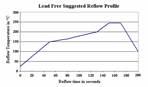
The HTU21D (F) sensor is qualified to withstand one lead free reflow soldering recommended process profile below according to JEDEC standard.
Mount parts within 24 hours after printing solder paste to avoid potential dry up.
For manual soldering, contact time must be limited to 5 seconds at up to 350°C.
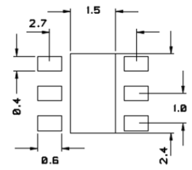
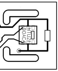
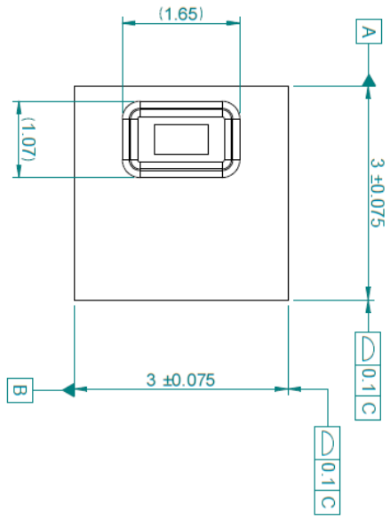
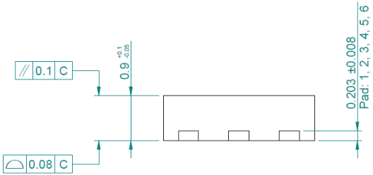
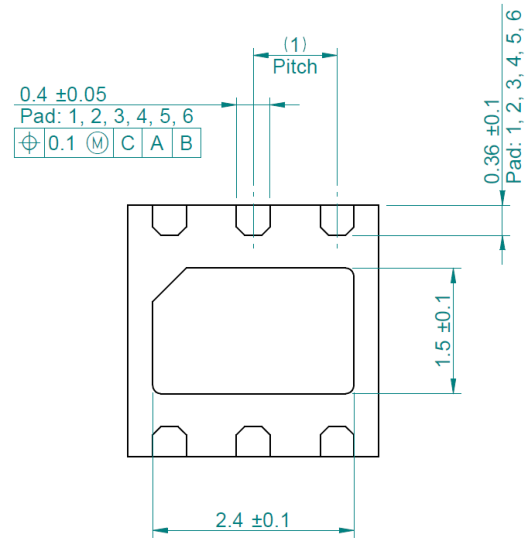
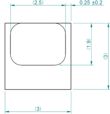
For the design of the HTU21D(F) sensor footprint, it is recommended to use dimensions according to figure below.
Recommended footprint for HTU21D(F) sensors. Values in mm.
No specific conditioning of devices is necessary after soldering process, either manual or reflow soldering. Optimized performance in case of metrological measurements can be reached with stabilization of devices (24 hours at 25°C / 55%RH). Similar process is advised after exposure of the devices to extreme relative humidity conditions.
In no case, neither after manual nor reflow soldering, a board wash shall be applied. Therefore, it is strongly recommended to use a “no-clean” solder paste. In case of applications with exposure of the sensor to corrosive gases or condensed water (i.e. environments with high relative humidity) the soldering pads shall be sealed (e.g. conformal coating) to prevent loose contacts or short cuts.
It is recommended to store HTU21D(F) sensor in its original packaging at following conditions: Temperature shall be in the range of -40°C – 125°C.
Relative humidity reading strongly depends on temperature. Therefore, it is essential to keep humidity sensors at the same temperature as the air of which the relative humidity is to be measured.
In case of testing or qualification the reference sensor and test sensor must show equal temperature to allow for comparing humidity readings.
The HTU21D(F) sensor should be mounted in a way that prevents heat transfer from electronic sensor or that keeps it as low as possible. Advice can be ventilation, reduction of copper layers between the HTU21D(F) sensor and the rest of the PCB or milling a slit into the PCB around the sensor (1mm minimum width).
Example of HTU21D(F) sensor mounting
with slits mills to minimize heat transfer
For sealing and gluing (use sparingly), use high filled epoxy for electronic packaging and silicone. For any specific material please request to humidity.application@meas-spec.com.
Window must remain uncovered.
Carrying the SCK and DATA signal parallel and in close proximity (e.g. in wires) for more than 10 cm may result in cross talk and loss of communication.
This may be resolved by routing VDD and/or GND between the two data signals and/or using shielded cables. Furthermore, slowing down SCK frequency will possibly improve signal integrity.
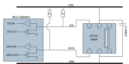
Power supply pins (VDD, GND) must be bypassed with a 100nF capacitor if wires are used. Capacitor should be placed as close as possible to the sensor.
Latch-up immunity is provided at a force current of ±100mA with Tamb=25°C according to JEDEC JESD78. For exposure beyond named limits the sensor need additional protection circuit.
Typical application circuit, including pull-up resistor Rp and decoupling of VDD and GND by a capacitor.
The supply voltage of HTU21D(F) sensors must be in the range of 1.5VDC - 3.6VDC. Recommended supply voltage is 3VDC (regulated).
However the typical application circuit includes a pull-up resistor R on data wire and a 100nF decoupling capacitor between VDD and GND, placed as close as possible to the sensor.
SCK is used to synchronize the communication between microcontroller and HTU21D(F) sensor. Since the interface consists of fully static logic there is no minimum SCK frequency.
An external pull-up resistor (e.g. 10kΩ) on SCK is required to pull the signal high only for open collector or open drain technology microcontrollers. In most of the cases, pull-up resistors are internally included in I/O circuits of microcontrollers.
Characteristics Symbol Min Typ Max Unit
Low level output
-4mA<IOL<0mA VOL 0 - 0.4 V
voltage
Capacitive load on bus line C B 0 - 500 pF
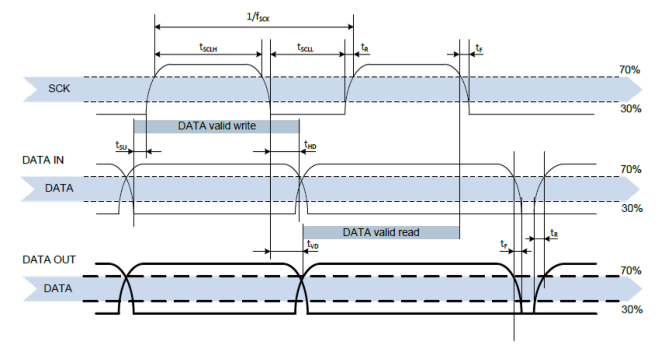
DATA directions are seen from the HTU21D(F) sensor. DATA line in bold is controlled by the sensor. DATA valid read time is triggered by falling edge of anterior toggle.
The HTU21D(F) sensor requires a voltage supply between 1.5V and 3.6V. After power up, the device needs at most 15ms while SCK is high for reaching idle state (sleep mode), i.e to be ready accepting commands from the MCU. No command should be sent before that time. Soft reset is recommended at start, refer p.13.
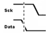
To initiate transmission, a start bit has to be issued. It consists of a lowering of the DATA line while SCK is high followed by lowering SCK.
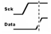
To stop transmission, a stop bit has to be issued. It consists of a heightening of the DATA line while SCK is high preceded by a heightening of the SCK.
For sample source code, please request to pic.info@te.com
After sending the start condition, the subsequent I²C header consist of a 7-bit I²C device address 0x40 and a DATA direction bit (‘0’ for Write access : 0x80). The HTU21D(F) sensor indicates the proper reception of a byte by pulling the DATA pin low (ACK bit) after the falling edge of the 8th SCK clock. After the issue of a measurement command (0xE3 for temperature, 0xE5 for relative humidity), the MCU must wait for the measurement to complete. The basic commands are given in the table below:
There are two different operation modes to communicate with the HTU21D(F) sensor: Hold Master mode and No Hold Master mode.
In the first case, the SCK line is blocked (controlled by HTU21D(F) sensor) during measurement process while in the second case the SCK line remain open for other communication while the sensor is processing the measurement.
No Hold Master mode allows for processing other I²C communication tasks on a bus while the HTU21D(F) sensor is measuring. A communication sequence of the two modes is available below.
In the Hold Master mode, the HTU21D(F) pulls down the SCK line while measuring to force the master into a wait state. By releasing the SCK line, the HTU21D(F) sensor indicates that internal processing is completed and that transmission may be continued.
In the No Hold Master mode, the MCU has to poll for the termination of the internal processing of the HTU21D(F) sensor. This is done by sending a start condition followed by the I²C header (‘1’ for Read access: 0x81) as shown below. If the internal processing is finished, the HTU21D(F) sensor acknowledges the poll of the MCU and data can be read by the MCU. If the measurement processing is not finished, the HTU21D(F) sensor answers no ACK bit and start condition must be issued once more.
For both modes, since the maximum resolution of the measurement is 14 bits, the two last least significant bits (LSBs, bits 43 and 44) are used for transmitting status information. Bit 1 of the two LSBs indicates the measurement type (‘0’: temperature, ‘1’: humidity). Bit 0 is currently not assigned. (Refer to Diagnostic Status for more information)
Checksum
Hold Master communication sequence
No Hold Master communication sequence
Grey blocks are controlled by HTU21D(F) sensor.
For Hold Master sequence, bit 45 may be changed to NACK followed by a stop condition to omit checksum transmission.
For No Hold Master sequence, if measurement is not completed upon “read” command, sensor does not provide ACK on bit 27 (more of these iterations are possible). If bit 45 is changed to NACK followed by stop condition, checksum transmission is omitted.
In those examples, the HTU21D(F) sensor output is S RH = ‘0111’1100’1000’0000 (0x7C80). For the calculation of physical values status bits must be set to ‘0’. Refer to “Conversion of signal outputs” section p.16.
The maximum duration for measurement depends on the type of measurement and resolution chosen. Maximum values shall be chosen for the communication planning of the MCU. Refer to the table p.4 and p.6 regarding measuring time specifications.
I²C communication allows for repeated start conditions without closing prior sequence with stop condition.
A sensor is defective, only if the diagnostic state remains when external conditions change.
This command is used for rebooting the HTU21D(F) sensor switching the power off and on again. Upon reception of this command, the HTU21D(F) sensor system reinitializes and starts operation according to the default settings with the exception of the heater bit in the user register. The soft reset takes less than 15ms.
The content of user register is described in the table below. Reserved bits must not be changed and default values of respective reserved bits may change over time without prior notice. Therefore, for any writing to user register, default values of reserved bits must be read first.
The “End of Battery” alert/status is activated when the battery power falls below 2.25V.
The heater is intended to be used for functionality diagnosis: relative humidity drops upon rising temperature. The heater consumes about 5.5mW and provides a temperature increase of about 0.5-1.5°C.
OTP reload is a safety feature and load the entire OTP settings to the register, with the exception of the heater bit, before every measurement. This feature is disabled per default and it is not recommended for use. Please use soft reset instead as it contains OTP reload.
6 1 Status: End of Battery (1) ‘0’: VDD>2.25V ‘1’: VDD<2.25V
‘0’
(1) This status bit is updated after each measurement
Cut-off value for “End of Battery” signal may vary by ±0.1V.
Reserved bits must not be changed.
OTP reload active loads default settings after each time a measurement command is issued.
Register Content to be written
CRC stands for Cyclic Redundancy Check. It is one of the most effective error detection schemes and requires a minimal amount of resources.
The types of errors that are detectable with CRC that is implemented in HTU21D(F) sensors are:
A CRC is an error-detecting code commonly used in digital networks and storage devices to detect accidental changes to raw data.
Blocks of data entering these systems get a short check value attached, based on the remainder of a polynomial division of their contents; on retrieval the calculation is repeated, and corrective action can be taken against presumed data corruption if the check values do not match.
CRCs are so called because the check (data verification) value is a redundancy (it expands the message without adding information) and the algorithm is based on cyclic codes. CRCs are popular because they are simple to implement in binary hardware, easy to analyze mathematically, and particularly good at detecting common errors caused by noise in transmission channels. Because the check value has a fixed length, the function that generates it is occasionally used as a hash function.
CRC for HTU21D(F) sensors using I²C Protocol
When HTU21D(F) sensors are run by communicating with the standard I²C protocol, an 8-bit CRC can be used to detect transmission errors. The CRC covers all read data transmitted by the sensor. CRC properties for HTU21D(F) sensors communicating with I²C protocol are listed in the table below.
CRC with I²C protocol Generator polynomial X 8 + X 5 + X 4 + 1
CRC calculation
To compute an n-bit binary CRC, line the bits representing the input in a row, and position the (n+1)-bit pattern representing the CRC's divisor (called a "polynomial") underneath the left-hand end of the row.
This is first padded with zeroes corresponding to the bit length n of the CRC.
If the input bit above the leftmost divisor bit is 0, do nothing. If the input bit above the leftmost divisor bit is 1, the divisor is XORed into the input (in other words, the input bit above each 1-bit in the divisor is toggled). The divisor is then shifted one bit to the right, and the process is repeated until the divisor reaches the right-hand end of the input row.
Since the left most divisor bit zeroed every input bit it touched, when this process ends the only bits in the input row that can be nonzero are the n bits at the right-hand end of the row. These n bits are the remainder of the division step, and will also be the value of the CRC function.
The validity of a received message can easily be verified by performing the above calculation again, this time with the check value added instead of zeroes. The remainder should equal zero if there are no detectable errors.
CRC examples
The input message 11011100 (0xDC) will have as result 01111001 (0x79).
The input message 01101000 00111010 (0x683A: 44.8%RH) will have as result 01111100 (0x7C).
The input message 01001110 10000101 (0x4E85: 7.04°C) will have as result 01101011 (0x6B).
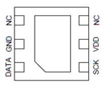
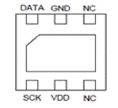
| N° | Function | Comment |
|---|---|---|
| 1 | DATA | Data bit-stream |
| 2 | GND | Ground |
| 3 | NC | Must be left unconnected |
| 4 | NC | Must be left unconnected |
| 5 | VDD | Supply Voltage |
| 6 | SCK | Selector for RH or Temp |
| PAD | Ground or unconnected |
| High level output voltage | VOH | 70%VDD | - | VDD | V |
|---|---|---|---|---|---|
| Low level input voltage | VIL | 0 | - | 30%VDD | V |
| High level input voltage | VIH | 70%VDD | - | VDD | V |
| Characteristics | Symbol | Min | Typ | Max | Unit |
|---|---|---|---|---|---|
| f SCK | 0 | - | 0.4 | MHz |
| SCK high time | SCKLH | µs | |||
|---|---|---|---|---|---|
| t SCLL | 1.3 | - | - | µs |
| DATA set-up time | t SU | ns | |||
|---|---|---|---|---|---|
| t HD | 0 | - | 900 | ns |
| DATA valid-tile | t VD | 0 | - | 400 | ns |
|---|---|---|---|---|---|
| t | 0 | - | 100 | ||
| SCK/DATA fall time | F | ns | |||
| t R | 0 | - | 300 | ns |
| Command | Code | Comment |
|---|---|---|
| Trigger Temperature Measurement | 0xE3 | Hold master |
| Trigger Humidity Measurement | 0xE5 | Hold master |
| Trigger Temperature Measurement | 0xF3 | No Hold master |
| Trigger Humidity Measurement | 0xF5 | No Hold master |
| Write user register | 0xE6 | |
| Read user register | 0xE7 | |
| Soft Reset | 0xFE |
| 1 2 3 4 5 6 7 8 9 | 10 11 12 13 14 15 16 17 18 |
|---|---|
| S 1 0 0 0 0 0 0 0 ACK | 1 1 1 0 0 1 0 1 ACK |
| I²C address + write | Command (see table p.9) |
| 19 20 21 22 23 24 25 26 27 | |
| S 1 0 0 0 0 0 0 1 ACK | Measurement |
| I²C address + read | Hold during measurement |
| 28 29 30 31 32 33 34 35 36 | 37 38 39 40 41 42 43 44 45 |
| 0 1 1 1 1 1 0 0 ACK | 1 0 0 0 0 0 1 0 ACK |
| Data (MSB) | Data (LSB) Status |
| 46 47 48 49 50 51 52 53 54 | |
| 1 0 0 1 0 1 1 1 NACK | P |
| 1 2 3 4 5 6 7 8 9 | 10 11 12 13 14 15 16 17 18 |
|---|---|
| S 1 0 0 0 0 0 0 0 ACK | 1 1 1 1 0 1 0 1 ACK |
| I²C address + write | Command (see table p.9) |
| 19 20 21 22 23 24 25 26 27 | |
| Measurement S | 1 0 0 0 0 0 0 1 NACK |
| measuring | I²C address + read |
| 19 20 21 22 23 24 25 26 27 | |
| Measurement S | 1 0 0 0 0 0 0 1 ACK |
| continue measuring | I²C address + read |
| 28 29 30 31 32 33 34 35 36 | 37 38 39 40 41 42 43 44 45 |
| 0 1 1 1 1 1 0 0 ACK | 1 0 0 0 0 0 1 0 ACK |
| Data (MSB) | Data (LSB) Status |
| 46 47 48 49 50 51 52 53 54 | |
| 1 0 0 1 0 1 1 1 NACK | P |
| DATA | MSB | DATA | LSB | Status Bit | ||
|---|---|---|---|---|---|---|
| 00 00 00 00 | 00 00 00 | 00 | Diag State (Open circuit) | |||
| XX XX XX XX | XX XX XX | 00 | Temperature data | |||
| XX XX XX XX | XX XX XX | 10 | Humidity data | |||
| 11 11 11 11 | 11 11 11 | 11 | Diag State (Short Circuit) |
| 1 2 3 4 5 6 7 8 9 10 11 12 13 14 | 15 16 17 18 |
|---|---|
| S 1 0 0 0 0 0 0 0 ACK 1 1 1 1 1 | 1 1 0 ACK P |
| I²C address + write Soft Reset Command |
| Bit | #Bits | Description/Coding | Default |
|---|---|---|---|
| 7,0 | 2 | Measurement resolution | ‘00’ |
| Bit 7 | Bit 0 | RH | Temp |
|---|---|---|---|
| 0 | 0 | 12 bits | 14 bits |
| 0 | 1 | 8 bits | 12 bits |
| 1 | 0 | 10 bits | 13 bits |
| 1 | 1 | 11 bits | 11 bits |
| 3, 4, 5 | 3 | Reserved | ‘0’ |
|---|---|---|---|
| 2 | 1 | Enable on-chip heater | ‘0’ |
| 1 | 1 | Disable OTP reload | ‘1’ |
| 1 2 3 4 5 6 7 8 9 | 10 11 12 13 14 15 16 17 18 |
|---|---|
| S 1 0 0 0 0 0 0 0 ACK | 1 1 1 0 0 1 1 1 ACK |
| I²C address + write | Read Register Command |
| 19 20 21 22 23 24 25 26 27 | 28 29 30 31 32 33 34 35 36 |
| S 1 0 0 0 0 0 0 1 ACK | 0 0 0 0 0 0 1 0 NACK |
| I²C address + read | Register content |
| 37 38 39 40 41 42 43 44 45 | 46 47 48 49 50 51 52 53 54 |
| S 1 0 0 0 0 0 0 0 ACK | 1 1 1 0 0 1 1 0 ACK |
| I²C address + write | Write Register Command |
| 55 56 57 58 59 60 61 62 63 | |
| 0 0 0 0 0 0 1 1 ACK | P |
| Generator polynomial | 8 5 4 |
|---|---|
| X + X + X + 1 | |
| Initialization | 0x00 |
| Protected data | Read data |
| Final Operation | none |
Default resolution is set to 12-bit relative humidity and 14-bit temperature readings. Measured data are transferred in two byte packages, i.e. in frames of 8-bit length where the most significant bit (MSB) is transferred first (left aligned). Each byte is followed by an acknowledge bit. The two status bits, the last bits of LSB, must be set to ‘0’ before calculating physical values.
To accommodate/adapt any process variation (nominal capacitance value of the humidity die), tolerances of the sensor above 100%RH and below 0%RH must be considered. As a consequence:
With the relative humidity signal output SRH, the relative humidity is obtained by the following formula (result in %RH), no matter which resolution is chosen:
In the example given p.10, the transferred 16-bit relative humidity data is 0x7C80: 31872. The relative humidity results to be 54.8%RH.
The temperature T is calculated by inserting temperature signal output STemp into the following formula (result in °C), no matter which resolution is chosen:
The dew point is the temperature at which the water vapor in the air becomes saturated and condensation begins.
The dew point is associated with relative humidity. A high relative humidity indicates that the dew point is closer to the current air temperature. Relative humidity of 100% indicates that the dew point is equal to the current temperature (and the air is maximally saturated with water). When the dew point stays constant and temperature increases, relative humidity will decrease.
Dew point temperature of the air is calculated using Ambient Relative Humidity and Temperature measurements from HTU21D(F) sensor with following formulas given below:
Partial Pressure (PP Tamb ) formula from Ambient Temperature:
) ( 10
C Tamb
Tamb PP
Tamb
amb
A, B, C Constants: A=8.1332; B=1762.39; C=235.66
| Dew point Temperature (T | ) formula from Partial Pressure (PP | ): |
|---|---|---|
| d | Tamb |
| PP Tamb | Partial Pressure in mmHg at ambient temperature (T | amb ) |
|---|---|---|
| RH amb | Ambient humidity in %RH, computed from HTU21D(F) sensor | |
| T amb | Humidity cell temperature in °C, computed from HTU21D(F) sensor | |
| T | Calculated Dew Point in °C |
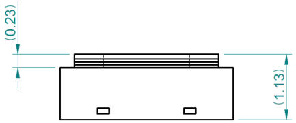
Dimensions are given in mm, tolerances are ±0.1mm. The die pad (thermal center pad) is internally connected to GND.
The HTU21D(F) sensor chip is mounted to a lead frame made of Cu and plated with Ni/Pd/Au. Chip and lead frame are over molded by green epoxy-based mold compound. Please note that side walls of sensors are diced and hence lead frame at diced edge is not covered with respective protective coating.
The total weight of the sensor is 0.025g.
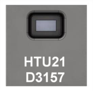
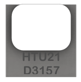
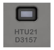
o The first digit of the second line defines the output mode:
D or A = digital and I²C
o The second digit defines the manufacturing year: 3 = 2013, 4 = 2014, etc.
o The last three digits represent an alphanumeric tracking code. That code represents the day of the year.
Laser marking on HTU21D(F) sensor
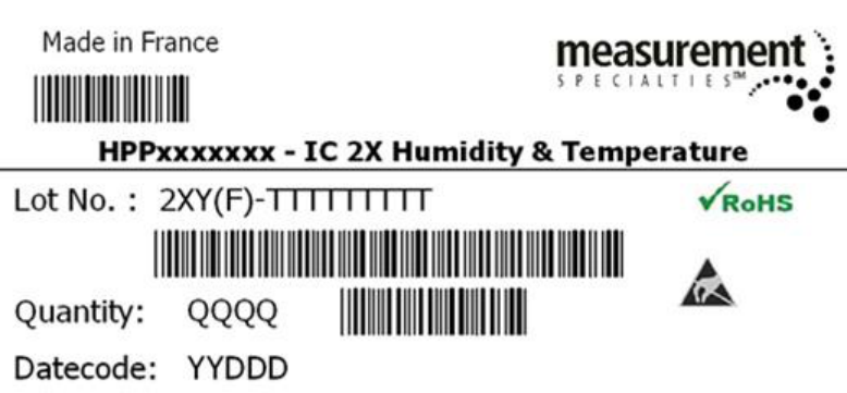
Reels are also labeled, as displayed below and give additional traceability information.
With:
2X: Sensor Type (21 for HTU21)
Y: Output mode (D/A = Digital, P = PWM)
(F): Sensor with PTFE membrane option
TTTTTTTTT: MEAS Traceability Code
QQQQ: Quantity per reel (400, 1500 or 5000 units)
YY: Last two digits of the year
DDD: Day of the year
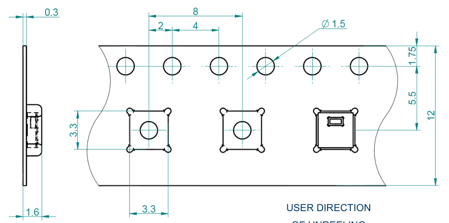
Standard packaging sizes are 400, 1500 and 5000 units per reel. Each reel contains 440mm (55 pockets) header tape and 200mm (25 pockets) trailer tape. The drawing of the packaging tapes with sensor orientation is shown in the picture below.
In order to use and preserve the high quality performance of the HTU21 humidity and temperature sensor, the following recommendations have to be followed concerning storage and packaging.
Please read the paragraph below carefully and note that all precautions are applicable for design phases, production phases as well as in case of returned material to Measurement Specialties.
When sensors are not used or assembled, we recommend to store them in their original sealed anti ESD packaging. If sensors have been removed from their original packaging, we recommend to keep them into anti static shielded ESD bags.
Such SMD sensors is classified MSL level 1 according to IPC/JEDEC J-STD-020.1 for storage, packaging and handling.
We recommend a shelf life of 1 year in following conditions of temperature and relative humidity ≤30°C 85%RH.
Protection against ESD mandatory


Package: TAPE AND REEL M.P.Q OF 400 PIECES, 1500 PIECES or 5000 PIECES
** HTU21DF – I.C 21DF RH/T DIGITAL with ptfe membrane **
** I.C 21D DEMOKIT – WPP100B001: BLE Sensor Tag Demo for use with free Android or iOS application **
** I.C 21D DEMOKIT – WPP109B001: BLE Sensor Tag Demo for use with USB dongle Key for Windows PC **
For detailed information, please request to pic.info@te.com .
HTU21DF product with embedded PTFE membrane reference added, Storage conditions after soldering process updated (typing error), ESD performances updated,
“Conversion of signal outputs” paragraph, information on tape and reel packaging added, HTU21D demokit availability information added.
3 Correction of I²C communication reading and writing, correction of soldering peak temperature M.ROBERT October 2013
4 Obsolescence of HTU21S (SDM interface) version External package dimensions update M.ROBERT January 2014
Diagnostic paragraph added MSL level 1 informed Sensor dimension updated DEMOKIT ordering information updated
P.METRAL December 2015
8 CRC example correction. P.METRAL February 2016
Measurement Specialties, Inc., a TE Connectivity company Tel: 800-522-6752 (option 2) Email: customercare.ando@te.com
MEAS France SAS, a TE Connectivity company Tel: 800-440-5100 Email: customercare.tlse@te.com
Measurement Specialties (China) Ltd., a TE Connectivity company Tel: 0400-820-6015 Email: customercare.chdu@te.com
TE.com/sensorsolutions
Measurement Specialties, Inc., a TE Connectivity company.
TE Connectivity, TE, TE connectivity (logo) are trademarks. All other logos, products and/or company names referred to herein might be trademarks of their respective owners.
The information given herein, including drawings, illustrations and schematics which are intended for illustration purposes only, is believed to be reliable. However, TE Connectivity makes no warranties as to its accuracy or completeness and disclaims any liability in connection with its use. TE Connectivity‘s obligations shall only be as set forth in TE Connectivity‘s Standard Terms and Conditions of Sale for this product and in no case will TE Connectivity be liable for any incidental, indirect or consequential damages arising out of the sale, resale, use or misuse of the product. Users of TE Connectivity products should make their own evaluation to determine the suitability of each such product for the specific application.
© 2017 TE Connectivity Ltd. family of companies All Rights Reserved.
| Edition | Comments | Who | Date |
|---|---|---|---|
| 0 | Document creation | D. LE GALL | April 12 |
| A | General update | D. LE GALL-ZIRILLI | February 13 |
| updated | (typing | error), | ESD performances | updated, | ||||
|---|---|---|---|---|---|---|---|---|
| 2 | complementary | information | on RH | output | signal | in D. LE GALL-ZIRILLI | July 13 |
| 5 | Part number and designation modification | M.ROBERT | April 2014 |
|---|---|---|---|
| 6 | General update | M.ROBERT | October 2014 |