


In fixed gas detectors, online water analyzers and IAQ modules, “accurate sensor but random reboots” often traces to power—not sensing ICs. Long 24V feeds, switching noise on ADC references, and poor light-load efficiency on battery nodes are typical culprits. Senseiot treats PMIC/DC-DC as a first-class subsystem when integrating CO₂, multi-gas and humidity modules. This article follows design patterns seen in compact synchronous bucks such as the TPS54202 class, from schematic to factory test.

Field inputs: 24V, PoE and batteries—when sync buck wins
Plants commonly use 12V/24V DC buses; buildings may use PoE or 48V followed by step-down. Internally, nodes need 3.3V digital, 5V analog front ends or ±12V excitation. Dropping 24V to 3.3V with an LDO works at low current, but Wi-Fi/cellular bursts make LDO loss and temperature rise unacceptable.
Synchronous buck converters excel around 0.5–3A loads in centralized power architectures. Check input range, duty-cycle limits, and whether light-load modes (PFM) add audible noise or output spikes.
For 50–100mA MCU-only nodes, integrated bucks like TPS54202DDCR fit 4.5–28V inputs compactly. If isolated RS485 is required, partition isolated power and buck grounds deliberately.
Output ripple and ADC: a hidden accuracy killer
Electrochemical gas, NDIR CO₂ and precision humidity front ends are sensitive to AVDD/reference ripple. Switching harmonics coupled into analog paths show up as jitter or baseline drift that varies with temperature—often invisible on lab bench supplies.
Use secondary LC or ferrite filtering on analog rails; dedicate an LDO for ADC reference; single-point analog ground return. Measure ripple under real pulsed loads (radio TX, valve drivers), not idle conditions.
Senseiot modules define acceptance limits (e.g., ripple <10mVpp @100kHz) and factory spot checks for reading stability during wireless transmit.

PCB layout: SW node, loop area and thermal pad
Minimize high di/dt loops: input cap, high-side FET, inductor and return path stay tight. SW copper is both loss path and antenna—follow reference placement rather than moving inductors casually.
QFN/SON bucks like TPS54202 rely on bottom thermal pads. Via arrays and copper pour drive junction temperature; validate load regulation at 60°C or in hot soak for -40–85°C industrial ratings.
Keep bucks away from antennas or RS485 runs; use ground stitching or spacing, and pick switching frequency bands with EMI headroom.
EMI and reliability: conducted, radiated and surges
CE/FCC or pre-compliance often fails on conducted EMI from weak input filters or output ripple feedthrough; radiation ties to SW nodes and cable antennas. Common-mode chokes and Y caps must respect leakage limits—stricter in medical and commercial buildings.
24V plants see inductive kickback and indirect lightning. Input TVS, reverse protection and UVLO/EN thresholds define whether the node latches off. Document sustained input and surge ratings aligned with upstream breakers.
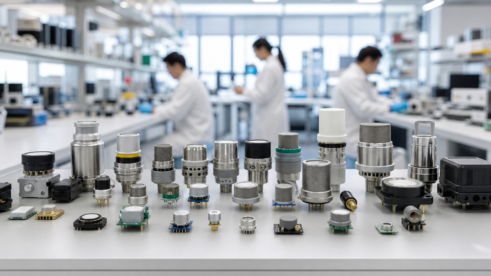
When browsing the sensor catalog, evaluate modules with pre-validated power sub-boards to reuse EMC work.


Multi-rail sequencing: MCU, sensing and comms wake order
Complex nodes may need 3.3V MCU, 5V sensor heaters and ±12V bridges. Buck-plus-LDO cascades are common; multiple bucks need sequencing—MCU boot before analog warm-up can trigger false alarms.
PMICs or reset supervisors chain power-good signals; firmware delays before enabling heaters or radios are low-cost sequencing. Fixed industrial gas safety devices often require defined power-on self-test windows (30–180s).
Production test and O&M: catch power issues before shipment
Factory tests should include input margining (18–28V), load efficiency spot checks, ripple sampling, and cold/hot start cycles. Battery nodes need sleep quiescent and wake latency metrics.
Field cases of “fixed after adapter swap” usually mean UVLO mismatch—label adapter voltage, ripple and current on nameplates; publish alternate BOM for inductors and input capacitors.
Designing the next data logger? Submit load profiles and EMC targets via request a quote or contact support for PMIC architecture review with Senseiot modules.